37.4 Lenticular displays⧉
Stereo glasses and headsets all share an inconvenience: you have to wear something. The dream of autostereoscopic display is to get depth from a bare screen, that is, glasses-free 3-D, where you simply look and see in three dimensions. The trick that makes it possible is to stop thinking of a screen as something that emits one image in all directions, and start thinking of it as something that can emit a different image in each direction. If the screen sends one picture toward where your left eye is and a different picture toward where your right eye is, then the routing that Chapter 37.1, Stereo glasses, did with filters and the headset did with two separate panels happens in the screen itself, automatically, for whoever is standing in front of it.
Two optical elements achieve this directional emission, and both work by putting a thin structure in front of a high-resolution panel so that each eye, from its angle, sees a different set of pixel columns.
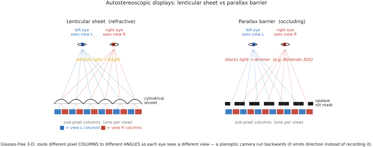
Lenticular sheet. A sheet of long, thin cylindrical lenslets (lenticules) is laid over the panel, one lenslet spanning a small group of pixel columns. Because a lens bends light by angle, each lenslet sends the column directly beneath it straight out, the column to its left out at one angle, the column to its right out at another, so the several columns under one lenslet are fanned out into different directions. Arrange the content so that column 1 of every group carries "view 1," column 2 carries "view 2," and so on, and the screen emits view 1 toward one angle, view 2 toward the next, and so forth. An eye at a given position intercepts whichever view is aimed its way; your two eyes, at different positions, catch different views, producing disparity, with no glasses.
Parallax barrier. The same directional routing, achieved by blocking instead of bending. Put an opaque mask with fine vertical slits a small distance in front of the panel; from a given viewing angle, each slit only lets you see the pixel columns lined up behind it along your line of sight, hiding the rest. Shift your eye and the slits reveal a different set of columns. So the barrier, too, sends different columns to different angles, the cheaper, lower-tech route. The trade-off is light: a barrier throws away most of the panel's light (the opaque bars block it), so barrier displays are dimmer, whereas a lenticular sheet redirects light and stays bright. Nintendo's 3DS handheld (2011) is the best-known parallax-barrier product, using a switchable barrier you could turn off to get a normal 2-D screen, while RED Hydrogen One and Leia displays pursued related directional-display approaches. Amazon's Fire Phone instead used head tracking to change a conventional screen's perspective; it did not route distinct simultaneous views to the two eyes.
37.4.1 Lippmann's integral photography: the common ancestor⧉
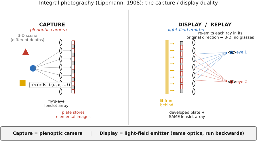
This chapter makes the capture/display duality explicit. In 1908 Gabriel Lippmann proposed integral photography Lippmann 1908: photograph a scene through a sheet of many tiny lenses (a fly's-eye array) onto a single plate, so each lenslet records its own small elemental image from a slightly shifted viewpoint. The plate ends up storing not just where light came from but which direction it came from, giving a sampling of the Chapter 31.1, Light fields 101 $L(u,v,s,t)$. That forward use of the fly's-eye array is the plenoptic camera of Chapter 31.2, Light field cameras. The backward use is the autostereoscopic display: develop the plate (or compute the equivalent image), lay it behind the same lenslet array, light it from behind, and each lenslet re-emits the rays it recorded, back in their original directions, reconstructing a sampled ray field as an emitter. Correct depth orientation also requires the appropriate elemental-image arrangement; naive replay can produce pseudoscopic, depth-reversed imagery. Two eyes at different positions intercept different ray bundles, see parallax-correct views, and perceive depth, glasses-free.
So a lenticular (or fly's-eye integral) display is, precisely, a plenoptic camera run backwards. The optics are the same, the 4-D object is the same, and only the direction of light is reversed. This is the single most important idea of the part, and it is why a 3-D display deserves to be called a light-field emitter: capture and display are duals, and everything you learned about sampling the light field on the camera side has a mirror image here.
37.4.2 Multi-view, and the resolution–views tradeoff⧉
With just two views routed to two angles, the display serves stereo to a viewer standing in one spot. Devote more of the pixel columns under each lenslet to more views (view 1, 2, 3, … 8, 9) and you get multi-view autostereo: as you move your head sideways, you cross from one view's zone into the next, and the picture changes, so you can look around the object a little. This is automultiscopic display: glasses-free and motion-parallax (rung 2 of the part's ladder, without a headset). Almost all such displays simplify to horizontal parallax only: they fan views left-to-right but not up-and-down, because we view the world side by side with two horizontally-separated eyes, and giving up vertical parallax saves an enormous amount of resolution.
The central trade-off is resolution versus number of views. The lenslet does not create pixels; it partitions the ones the panel already has. Every column you reserve to carry a distinct view is a column you are not using to make the underlying 2-D image sharper. So spatial resolution is spent to buy angular views: a panel that would show a sharp single image of $N$ pixels across, used to show $k$ views, shows each view at roughly $N/k$ pixels across. Want more viewpoints (smoother look-around)? You pay in sharpness. Want a crisp image? You get few views. This is exactly the Chapter 31.2, Light field cameras of the plenoptic camera, where fine angular sampling cost spatial resolution out of a fixed pixel budget, now running in reverse on the emitter: the conserved budget is the same, the choice is the same, only the arrow of light is flipped. Real displays also have a finite set of viewing zones (sweet spots where the views line up correctly) separated by regions where you see the wrong views or two views at once (crosstalk), and the views repeat periodically across angle, so the look-around is comfortable only within a sweet-spot.
Matusik and Pfister's 3D-TV system (2004) Matusik & Pfister 2004 built the full pipeline end to end: an array of cameras captured a multi-view light field of a live scene, and an array of projectors illuminating a lenticular display screen displayed it autostereoscopically, making capture and display one light-field system, exactly the duality made into an apparatus. More recent designs squeeze more out of the fixed budget with compressive / tensor light-field displays (Wetzstein et al. 2012 Wetzstein et al. 2012): instead of one lenslet sheet, they stack several light-attenuating LCD layers and optimize (factor) the layer patterns so that the stack, by multiplicative combination, reproduces the target light field far better than a naive lenslet split. This is a computational display that trades brute-force resolution for optimization.
37.4.3 Light-field telepresence: Google Starline⧉
The duality is no longer just a lab curiosity. Google's Project Starline (announced 2021) is a 3-D telepresence "magic window": an array of cameras and depth sensors captures a person, software reconstructs them in 3-D, and a light-field display renders them life-size to the remote viewer with correct stereo and head-motion parallax, without a headset. Sit down across from it and the other person appears to be sitting across a real table, looking around solid in space; lean and you see them from a slightly different angle. It is the clearest demonstration that an autostereoscopic display is a light-field emitter, and that telepresence is, end to end, a capture-and-display light-field pipeline, with multiview/depth acquisition and reconstruction feeding a directional display. This does not require a microlens plenoptic camera or identical capture and display optics. (In 2025 Google announced the evolution of Project Starline into Google Beam.)
37.4.4 Display depth of field and antialiasing⧉
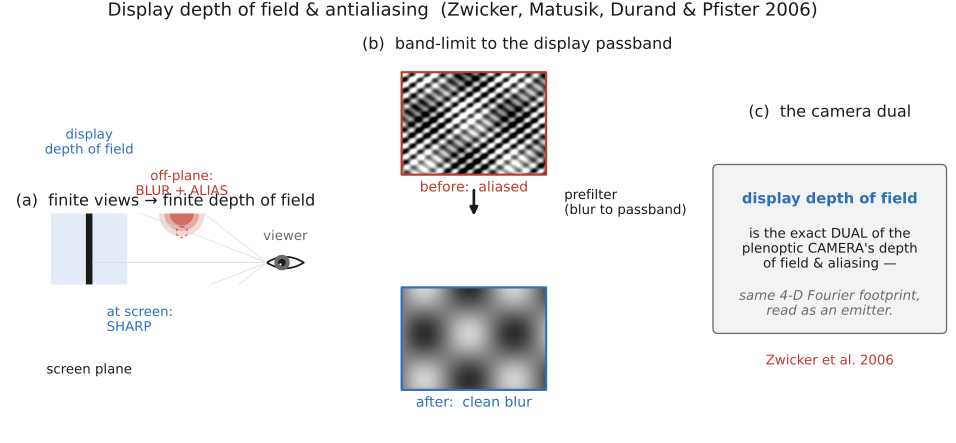
The reverse-arrow duality goes all the way down to aliasing. An automultiscopic display has only a finite number of views, a finite angular resolution, and that imposes a finite depth of field. Content right at the screen plane is sharp; but an object made to float far in front of or behind the screen must be painted by rapidly switching views as the eye moves, and with only a discrete set of views available, that switching beats against the scene's detail and the floating object blurs and aliases. These are the same staircase/moiré artifacts you would get from undersampling. There is a band of depth around the screen plane within which content stays sharp, and outside it things degrade: a display depth of field.
The fix is the dual of camera antialiasing: prefilter the light field before showing it. Band-limit the displayed light field to the display's spatio-angular passband. Blur it, in the right 4-D sense, down to what the finite views can faithfully carry, so that off-plane content fades into a graceful blur instead of an ugly aliased mess. Zwicker, Matusik, Durand, and Pfister worked this out in 2006 Zwicker et al. 2006 as antialiasing for automultiscopic 3-D displays, and the result is that the analysis is identical to the plenoptic camera's depth-of-field and aliasing analysis of Chapter 31.6, Light field aliasing and 4D Fourier analysis: the same 4-D Fourier footprint, the same band-limit, read as an emitter instead of a sensor. Capture and display are duals, and so are their failure modes.