22.1 Aberrations and optical challenges⧉
The thin lens of FUNDAMENTALS is simple: feed it a point of light and it gives you back a point. Every real lens disappoints that promise, and it does so in a number of characteristic ways. This part studies those failures: how they arise, how lens design reduces them, and how computation corrects what remains.
The organizing fact is simple. The thin lens is right only because it keeps just the first term of everything. Snell's law of refraction, $n_1\sin\theta_1 = n_2\sin\theta_2$, is non-linear, but for small angles $\sin\theta \approx \theta$ and it goes linear; that linearization is what makes a single focal length $f$ and the clean equation $1/f = 1/u + 1/v$ work. Restore the next term of the expansion,
and the cubic correction means rays through the edge of the aperture no longer land exactly where the central rays do. Let the refractive index depend on wavelength, $n(\lambda)$, a property called dispersion, and red and blue focus in different places. Add that real glass has thickness, real lenses have many surfaces, and real barrels have mounts, dust, and air gaps, and you have the full set of challenges below. Every one of them is geometry or physics the thin lens chose to ignore; manufacturing defects such as decentering can add further errors to these nominal-design limitations.
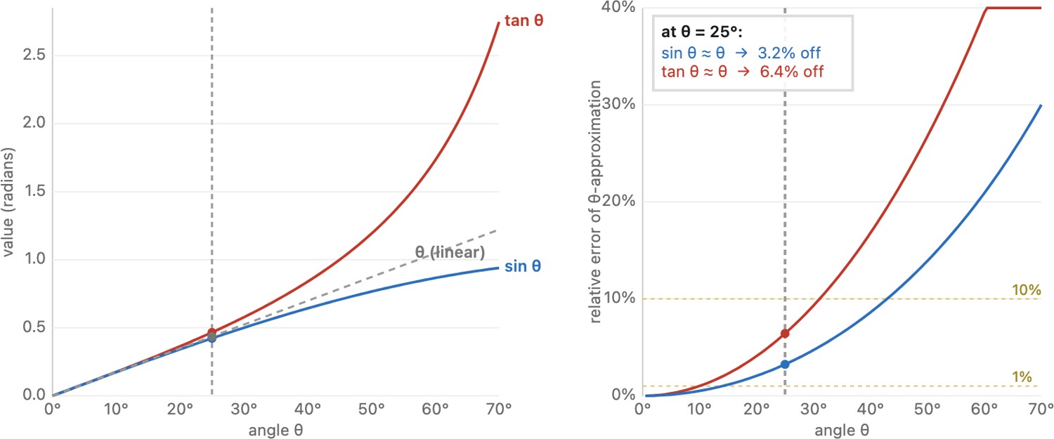
A piece of luck: the next term is cubic, not quadratic. Because $\sin\theta$ is an odd function, its Taylor series contains only odd powers (there is no $\theta^2$ term), so the first error in $\sin\theta\approx\theta$ is the cubic $\theta^3/6$, and likewise $\tan\theta\approx\theta$ errs only at order $\theta^3$. That single fact is why paraxial optics is so much better than it has any right to be: the linear model is accurate effectively to second order, not only first, with error that stays tiny over a surprisingly wide range of angles before the cubic term becomes significant (Figure 22.1.1). The flip side is that when it does break, it breaks as $\theta^3$. Those third-order terms are exactly the five so-called Seidel aberrations that organize this chapter.
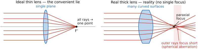
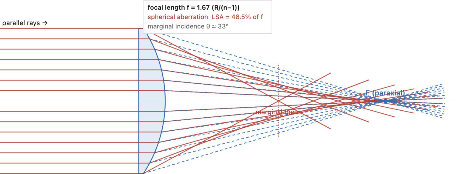
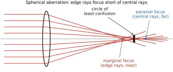
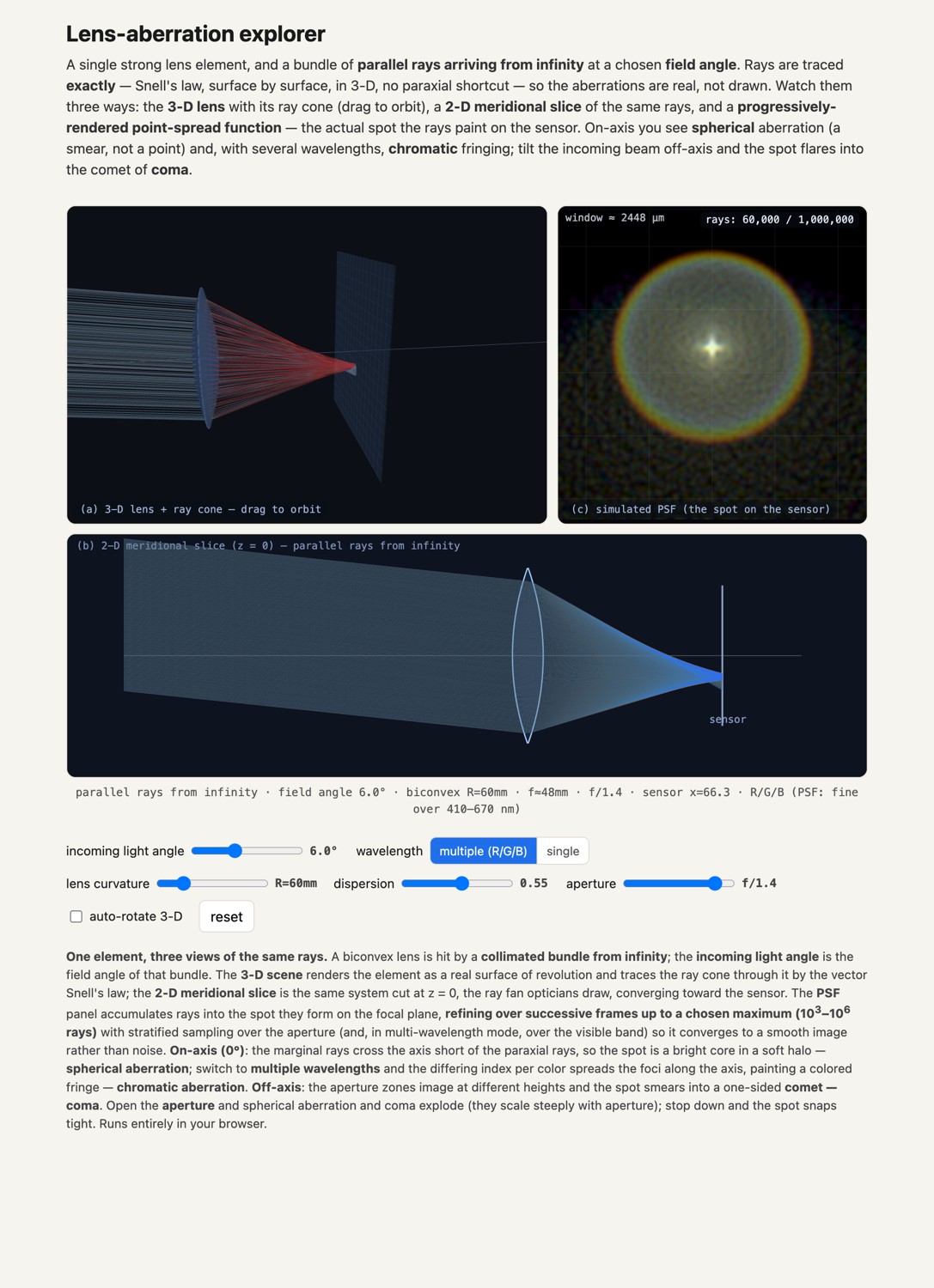
You can see the breakdown directly (Figure 22.1.3): trace a fan of parallel rays through a single lens in two ways: once with exact Snell refraction at the curved surface, and once with the paraxial thin-lens model that sends every ray through one focal point. Stopped down, the two are indistinguishable; opened up, the real marginal rays bend too hard and cross the axis short of the paraxial focus, and the single focus dissolves into a smear. The longitudinal gap between the rim focus and the paraxial focus is spherical aberration measured directly (the cubic term made visible), and you can shrink it by stopping down or raising the index, exactly the levers a real lens uses.
22.1.1 Taxonomy of challenges⧉
An ideal thin lens is summarized by one power or focal length. A physical singlet already has two surface curvatures, a thickness, and a glass choice; fixing its power still leaves some freedom to bend its shape. But a photograph demands that the lens satisfy many constraints at once: bring every field point to focus, at every wavelength, across the whole aperture, onto a flat sensor, with no stray light and no geometric warp. Those limited degrees of freedom cannot generally meet all these demands, which is the deep reason a real photographic lens is a stack of six, ten, or twenty elements (the subject of Chapter 22.5, A short bestiary of classic designs). The defects sort into a few families:
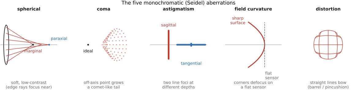
- Monochromatic aberrations: failures of geometry that survive even in a single color, because the spherical surfaces that are easy to grind are not the surfaces that focus perfectly. Third-order ray-aberration theory for a centered rotationally symmetric system organizes them into five Seidel families, the classical Seidel aberrations: spherical, coma, astigmatism, field curvature, and distortion. This chapter treats the ones with the most distinctive photographic signatures.
- Chromatic aberration (CA): a failure of color, because the index $n(\lambda)$ disperses, so each wavelength is effectively a slightly different lens.
- Wave effects: a limit set by the wave nature of light: even a geometrically perfect lens cannot beat diffraction, the fundamental blur set by the aperture and the wavelength.
- Radiometric and stray-light defects: vignetting (the image dims toward the corners) and flare (unwanted reflected and scattered light), which move or lose light energy rather than mis-focusing it.
A useful way to keep them straight is by what they do to the light. Most aberrations misplace energy: they take rays that should have met at a point and spread them into a blur, so they cost sharpness and you cannot perfectly undo them after the fact. Distortion is the exception: it keeps every point sharp and merely puts it in the wrong place, which is why it is the one defect that software corrects almost perfectly. Vignetting loses energy unevenly across the frame. Flare adds energy where it does not belong. We meet them in roughly that order. Throughout, the look of each defect, the spot it paints on the sensor, its point-spread function (PSF), the lens's answer to a single point of light, is summarized in the part's master figure.
22.1.2 Spherical aberration⧉
What it is. In a typical under-corrected positive spherical lens, rays that pass through the edge of the aperture are bent too strongly and cross the axis nearer the lens than rays through the center. There is no single focal plane: the marginal rays focus short, the paraxial rays focus long, and in between they form a waist of least confusion. This is the most direct consequence of keeping the cubic $\theta^3$ term. The sign can reverse in other prescriptions; the defining feature is the dependence of focus on pupil radius.
What it looks like. A soft, low-contrast image with a glowing halo around bright points and highlights: the sharp core sits on a luminous skirt of the mis-focused marginal rays. It is worst wide open, because that is when the aperture admits the outer rays at all, and it visibly cleans up as you stop down, which masks the offending edge of the lens. It also shows up as focus shift: the plane of best focus moves as you change aperture.
Why. The spherical surface, prized because any two pieces of glass ground against each other tend naturally toward a sphere, is simply the wrong shape for perfect focus; the correct surface is an asphere. The cure, an aspheric element or a split of optical power across several elements, is explained in Chapter 22.2, Aberrations correction. Some lenses leave it in on purpose: the dreamy soft-focus portrait look is under-corrected spherical aberration (see Chapter 22.7, Special optics).
22.1.3 Coma⧉
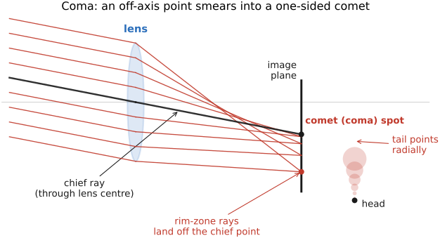
What it is. Coma is the off-axis cousin of spherical aberration: for a point that is not on the optical axis, the rays through different zones of the aperture image it at different magnifications, so instead of a clean point they pile up into a one-sided, comet-shaped smear (the name is from coma, a comet's tail). The blur is asymmetric. It has a bright head and a flaring tail pointing radially, toward or away from the center of the frame, which is what makes it so recognisable and so ugly.
What it looks like. Stars, streetlights, and specular highlights toward the edges and corners of the frame grow little wings or tails; a field of night-sky stars that are crisp dots in the center turn into tiny comets at the margins. Like spherical aberration it is worst wide open and improves on stopping down.
Why. It is one of the five Seidel terms, an inevitable consequence of the cubic expansion for off-axis points. It belongs to the family of odd aberrations that cancel by symmetry at unit-magnification symmetric conjugates in a system symmetric about the aperture stop. At infinity focus the cancellation is not automatic, but approximate symmetry remains a useful design starting point (the double-Gauss design, discussed in Chapter 22.5, A short bestiary of classic designs), which is exactly why symmetric designs dominate fast normal lenses. Full treatment of the cure is in Chapter 22.2, Aberrations correction.
22.1.4 Astigmatism⧉
What it is. Off-axis refraction can give different focusing powers in the meridional and sagittal ray sections, even after coma is corrected. This is not caused simply by an elliptical-looking aperture: detail oriented radially (the sagittal direction, pointing toward the frame center) and detail oriented tangentially (perpendicular to it) come to focus at two different depths. There is no single plane where both are sharp: at one focus the radial spokes of a wheel snap in while the rim blurs, and a little farther along it reverses. An off-axis point never collapses to a dot. It stretches into a short line that swings through ninety degrees as you rack focus.
What it looks like. You cannot get radial and tangential fine detail crisp at the same field position at once: a smear that changes orientation as you refocus, worst toward the corners. Together with field curvature (next), it is why uncorrected simple lenses are mushy off-center even when the middle is sharp.
Why. The third of the five Seidel terms, again a consequence of the cubic expansion off-axis. Its cure (balancing element powers and the placement of the stop, and trading it off against field curvature on the Petzval surface) is in Chapter 22.2, Aberrations correction.
22.1.5 Field curvature⧉
What it is. Even when every point is individually in sharp focus, the surface on which those sharp points lie is not flat. It is a bowl, the Petzval surface, curving toward or away from the lens. But the sensor is flat. So if you focus to make the center crisp, the corners fall off the curved focal surface and go soft; refocus for sharp corners and the center softens.
What it looks like. Center-sharp, corner-soft (or the reverse) in a way that no single focus setting fixes it. The softness is built into the geometry, not into where you put the focus ring. It is the bane of flat subjects like document copying, brick walls, and star fields, and it is why a "flat-field" lens is a prized and specially corrected thing.
Why. The fourth Seidel aberration, governed by the Petzval sum of the elements' powers and glasses. The cure is a dedicated field-flattener element near the focal plane, treated in Chapter 22.2, Aberrations correction.
22.1.6 Chromatic aberration⧉
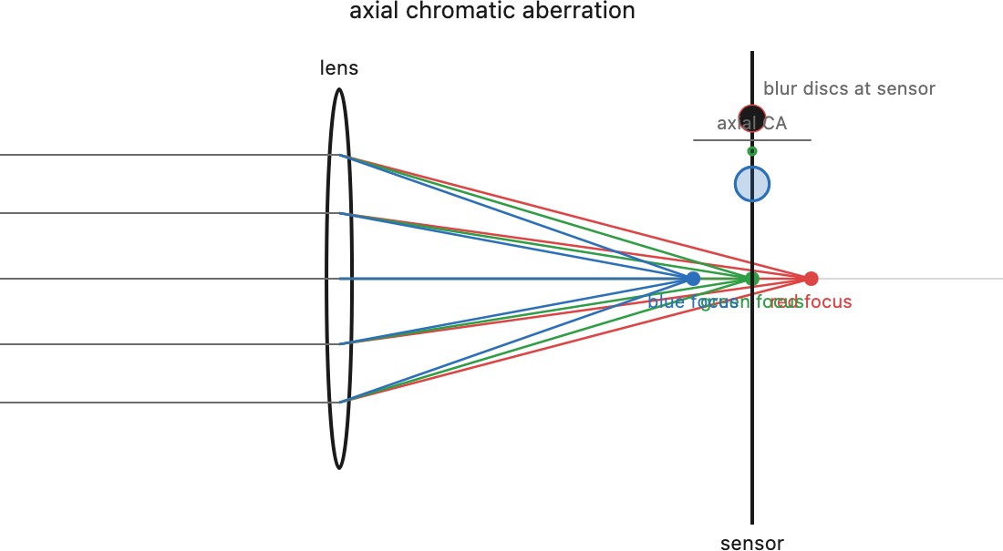
What it is. Glass bends blue light more than red because the refractive index falls with wavelength, a property called dispersion. So a lens has, in effect, a slightly shorter focal length for blue than for red, and the colors do not share a focus. The strength of a glass's dispersion is summarized by its Abbe number,
a ratio of the mid-spectrum refraction to the spread between blue ($F$) and red ($C$) lines; a high $V_d$ means low dispersion. Chromatic aberration (CA) comes in two flavors:
- Axial (longitudinal) CA: red, green, and blue focus at different depths along the axis. No single plane is sharp for all colors; each is slightly blurred by the others. It is worst at fast apertures and only partly relieved by stopping down.
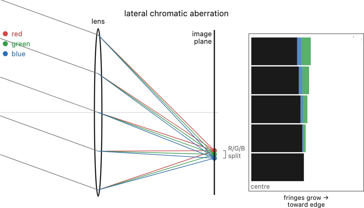
- Lateral (transverse) CA: the colors are imaged at different magnifications, so they line up at the center but spread apart toward the edges.
What it looks like. Axial CA gives color halos around high-contrast edges, classically a green-to-magenta glow that flips sign as you rack through focus, and it is a big contributor to the purple fringing you see on backlit branches and chrome trim (part CA, part sensor blooming and flare). Lateral CA gives colored fringes that grow toward the corners: a red edge on one side of a dark line and a blue edge on the other, strongest at the frame's margins and absent at the center.
Why. Purely the wavelength dependence $n(\lambda)$; it would vanish in a single-color world. The classic cure is the achromatic doublet, a low-dispersion crown element paired with a high-dispersion flint so the color errors cancel at two wavelengths, and, for the demanding cases, apochromats with special low-dispersion glasses. Lateral CA, being a per-color magnification error, is essentially a geometric rescale and is therefore highly correctable in software; axial CA, a genuine per-color blur, is not. The full story of both cures, in glass and in code, is in Chapter 22.2, Aberrations correction.
22.1.7 Radial distortion⧉
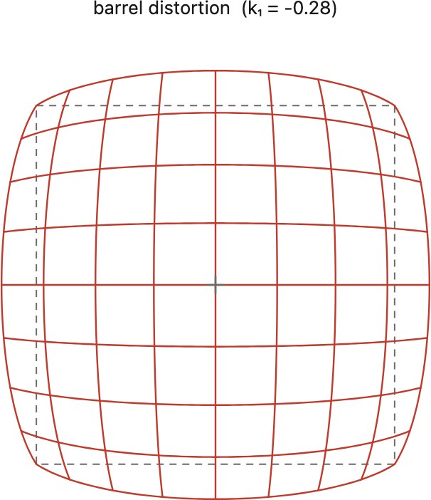
What it is. Distortion is the odd one out among aberrations: it does not blur anything. Every point stays perfectly sharp; the magnification simply varies with how far the point is from the center of the frame, so points land at the wrong radius. When magnification falls toward the edge, straight lines bow outward, barrel distortion (think of a barrel's bulging sides), typical of wide-angle lenses. When magnification grows toward the edge, lines bow inward, pincushion distortion, typical of telephotos. Zooms often do both at different focal lengths.
What it looks like. Straight edges that should be straight, such as the horizon, a building, a door frame, or the sides of the frame itself, curve gently. The effect is strongest near the frame edges and zero at the center; a square grid is the cleanest way to see it.
Why. A Seidel term, but a peculiar one: because it merely relocates sharp points along the radius rather than spreading their energy, it is the single most software-correctable defect in optics. A measured radial warp, a per-lens map of true radius to imaged radius, straightens the lines almost perfectly, which is why nearly every camera and phone ships with built-in distortion correction in the image pipeline. (It is also why a fisheye's dramatic barrel is treated not as an aberration but as an intended projection; see Chapter 22.7, Special optics.) The correction itself is detailed in Chapter 22.2, Aberrations correction.
The standard parametric models. The radial remapping is captured, for both lens-profile correction and camera calibration, by a low-order polynomial in the radius. Writing $r_u$ for the undistorted radius and $r_d$ for the distorted radius (both measured from the distortion center), the Brown–Conrady model Brown 1966 (Brown–Conrady) expands the distorted radius forward as
with optional tangential (decentring) terms $p_1, p_2$ for elements mounted slightly off-axis; $k_1<0$ gives barrel, $k_1>0$ pincushion. An alternative that inverts more cleanly, and that often captures even strong wide-angle distortion with a single parameter, is the division model (Fitzgibbon) Fitzgibbon 2001,
which is why it is popular in calibration pipelines. Either way the correction is a one-dimensional curve fit per lens; the mechanics live in Chapter 22.2, Aberrations correction.
22.1.8 Wave effects and diffraction⧉
What it is. Everything above treated light as rays. But light is a wave, and a wave passing through an aperture diffracts. It spreads. Even a geometrically perfect, aberration-free lens cannot focus a point to a point; the best it can do is a small bright disc ringed by faint haloes, the Airy pattern, whose angular scale is set by the wavelength $\lambda$ and the aperture diameter $D$:
This is a floor, not a defect of any particular lens. It is the diffraction limit. A bigger aperture (larger $D$) diffracts less; a smaller one diffracts more.
The pattern is the aperture's Fourier transform. More precisely, the diffraction pattern a point source makes is the Fourier transform of the aperture (its squared magnitude, to be precise; this is the point-spread function of a diffraction-limited lens). A round hole transforms into the Airy disc and its concentric rings; and because a wider function has a narrower transform, a bigger aperture makes a smaller spot, which is exactly the $\theta \approx \lambda/D$ limit, now read as a statement about Fourier transforms. The same fact explains sunstars, the radiating spikes around a bright streetlight or the sun in a stopped-down frame: they are the Fourier transform of the polygonal opening the diaphragm blades form, each straight blade-edge throwing a perpendicular streak of light, so an iris of $n$ blades makes a star with $n$ points when $n$ is even and $2n$ when $n$ is odd. This is the same Fourier transform that runs through Chapter 6.3, Linearity, Fourier, aliasing and deblurring. There it diagonalizes blur; here the lens computes one optically, in the time it takes light to cross the aperture.
What it looks like. Counterintuitively, stopping down, which cures the geometric aberrations above, eventually softens the whole image again, because the shrinking aperture raises the diffraction floor. Many lenses have a sharpness optimum below maximum aperture, with the location depending on field position, focus, wavelength, and the chosen metric, where the aberrations have mostly faded but diffraction has not yet taken over; close down further (a high f-number) and the picture goes uniformly mushy. Diffraction also caps the finest detail a sensor of given pixel size can usefully resolve.
Why. It comes from the wave nature of light, not a flaw in the glass, so it is a limit rather than a correctable defect. It connects forward to the part's recurring theme: because the smallest blur a lens can make is the diffraction spot, the PSF is never a true point, and engineering or inverting that PSF, by deconvolution, by coded apertures and wavefront coding, is the computational side of the story (forward-referenced to Chapter 22.2, Aberrations correction and the Advanced part). The full optics of the Airy pattern and the resolution limit belong to the Fourier-optics treatment cited below; here we only flag that the floor exists.
22.1.9 Vignetting⧉
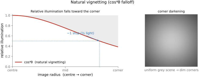
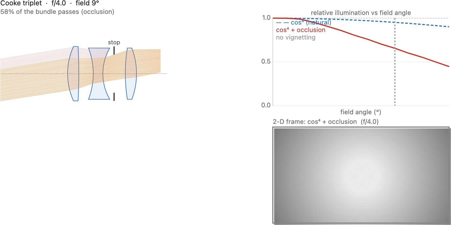
What it is. The image gets darker toward the corners. Two distinct mechanisms share the name. First, a geometric effect in the simple rectilinear model: light reaching the corner of the frame arrives at a steep angle and is dimmed by a factor of $\cos^4\theta$ (the natural or $\cos^4$ falloff introduced in FUNDAMENTALS, from the tilt of the pupil, the longer path, and the foreshortened aperture). Second, optical vignetting (sometimes mechanical vignetting): off-axis, the lens barrel and the front and rear elements partially block the aperture, clipping the bundle of light that would otherwise reach the corner.
What it looks like. A gradual darkening from a bright center to dim corners, strongest wide open for the optical component and largely independent of aperture for the $\cos^4$ component. Optical vignetting also reshapes the out-of-focus highlights near the edges into cat's-eye or lemon shapes (the clipped pupil), a bokeh effect developed in Chapter 23.1, Bokeh, focus stacking, and depth-of-field control. Stopping down shrinks the bundle enough to clear the obstructions, so corner brightness (and round bokeh) return.
Why. The $\cos^4$ law assumes the simple pupil and projection model; pupil distortion and lens design can change the falloff. The optical part is the finite size of the barrel and elements clipping the entrance pupil off-axis. Both produce a smooth radial brightness map, which is exactly what makes vignetting easy to undo: a measured radial gain map in the image pipeline lifts the corners back to match the center (at some cost in corner noise). That correction, together with the distinction from sensor- and microlens-induced falloff, is in Chapter 22.2, Aberrations correction.
22.1.10 Flare and coating⧉
What it is. Aberrations are wanted rays landing in the wrong place; flare is unwanted light reaching the sensor at all. At every air–glass surface a few percent of the light reflects instead of transmitting: about 4% per uncoated surface, from the Fresnel reflectance $R = \big((n_1-n_2)/(n_1+n_2)\big)^2$. In a lens with a dozen surfaces those stray reflections bounce around and arrive as junk light. A ray that reflects twice can refocus into a discrete, often aperture-shaped bright blob, called a ghost, typically strung along a line from a strong light source through the frame center. Many faint scatters and reflections sum into veiling glare, a low-frequency wash that lifts the blacks and crushes contrast.
What it looks like. Shooting into the sun or with a bright source just outside the frame: a chain of colored polygonal ghosts marching across the picture, streaks and stars, and an overall milky loss of contrast in the shadows. The more elements a lens has, the worse it would be. $N$ surfaces give $O(N^2)$ pairs of surfaces that can inter-reflect, one cost of the many-element designs the rest of the part relies on.
Why. Fresnel reflection at each interface. The thing that made many-element lenses practical is the anti-reflection coating: a thin transparent film with quarter-wave optical thickness at a design wavelength, $n_{\mathrm{film}}t=\lambda_0/4$ at normal incidence, whose two surface reflections interfere destructively and nearly cancel the reflection over a band, the faint colored sheen on a modern lens. Coatings drop per-surface reflection from ~4% toward a few tenths of a percent. The numbers compound. Through twelve uncoated surfaces the image keeps $0.96^{12}\approx 61\%$ of the light; at 0.5% per surface it keeps $0.995^{12}\approx 94\%$. A ghost needs two reflections, so its strength goes as the square of the reflectance: $0.04^2=1.6\times10^{-3}$ of the source uncoated against $0.005^2=2.5\times10^{-5}$ coated, 64 times weaker for each pair of surfaces. Alongside coatings, lens hoods and internal baffles keep stray off-axis light from entering in the first place. This chapter only names flare as one of the optical challenges; the physics of thin-film coatings, hoods, baffles, and computational deflare is the subject of Chapter 22.10, Glare suppression.
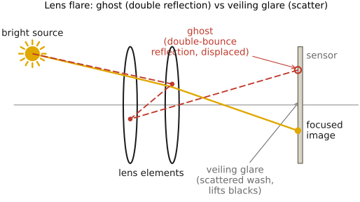
You can watch the ghosts form by tracing a single ray through a real lens (Figure 22.1.14).

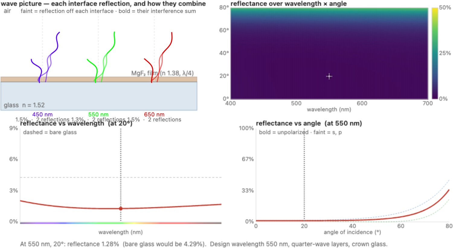
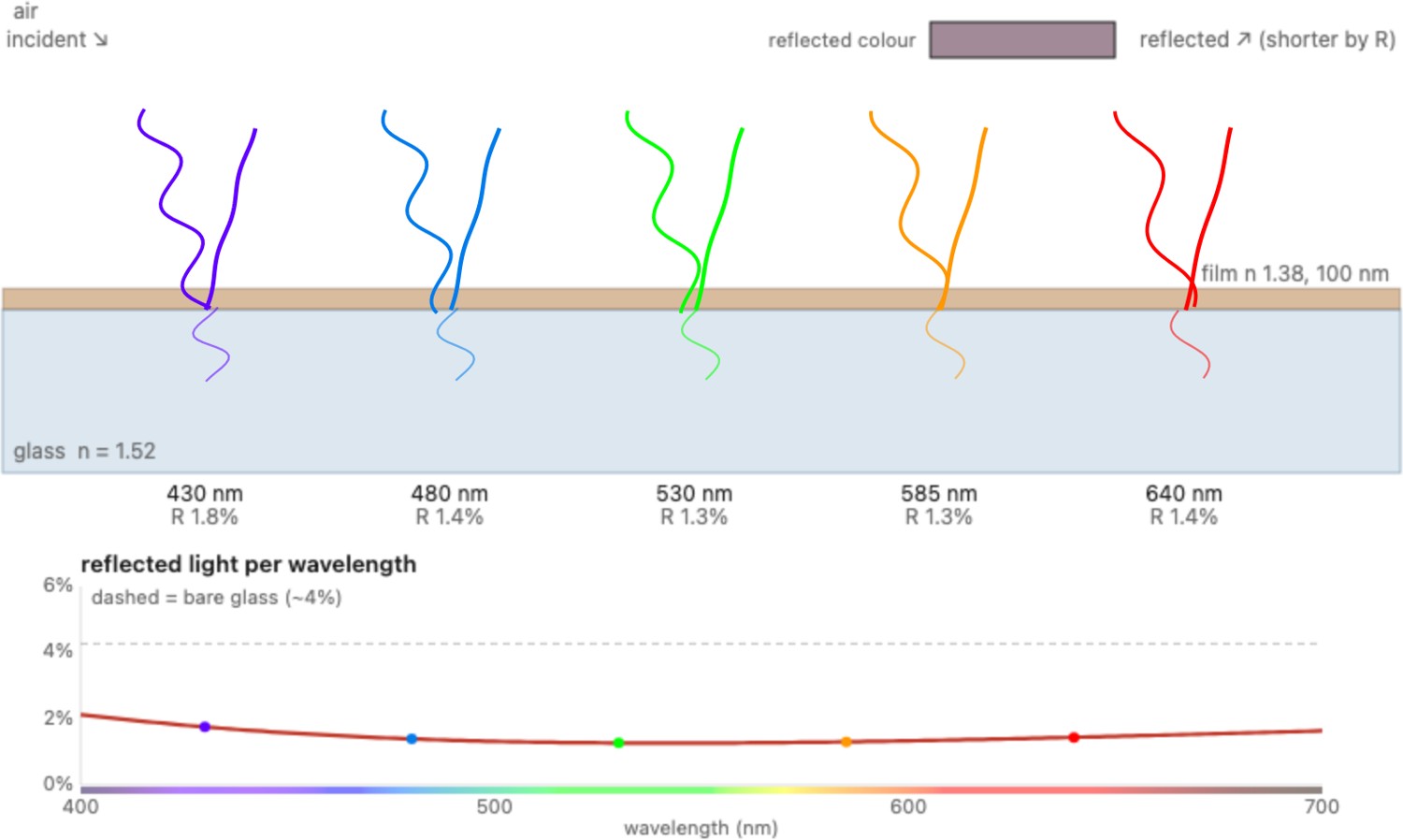
Seen quantitatively, the coating's quarter-wave trick is the same thin-film interference that colors a soap bubble (Chapter 2.1, Light and optics, Figure 2.1.33), now turned to the opposite use: instead of reinforcing a color it is tuned to cancel the reflection. Two interactive views make the mechanism concrete. The first plots the reflectance of bare, single-coated, and double-coated glass across the whole visible band and across the angle of incidence at once (Figure 22.1.15): a single quarter-wave film of magnesium fluoride cuts the ~4% bare-glass reflection to about 1% near its design wavelength, and a matched double layer (a low index over a higher one) drives it almost to zero across a band, while both climb back toward grazing incidence. The second rebuilds the soap-bubble wave picture as a coating on glass (Figure 22.1.16): five waves strike the surface and each reflected wave shrinks as you set the film thicknesses, nearly vanishing where the film's two surface reflections cancel, with the color of the leftover reflection shown as a swatch, the faint sheen of a coated lens.
Modern lenses push past the quarter-wave film, which has two limits: its ideal single-layer index is $\sqrt{n_\text{glass}}\approx 1.23$, below the index of most conventional dense coating materials, and a fixed film cancels only near one wavelength and one angle, so reflections return at the steep angles where ghosts are worst. Two families of nano-coating get around both. The first builds a film riddled with nanometer voids or hollow silica spheres, so its effective index is a blend of glass and air, low enough (around 1.1) to be the matching layer no bulk material provides: Nikon's Nano Crystal Coat uses gaps between nanoparticles, and Canon's Air Sphere Coating incorporates air in a silica-based film. Sony's Nano AR is another nanostructured anti-reflection technology; the trade names do not imply identical material or fabrication recipes. The second gives up the flat interface: a dense array of subwavelength wedges or cones a few hundred nanometers tall makes the index climb gradually from air to glass, so there is almost no boundary to reflect from, over a wide band and a wide range of angles. This is the moth-eye structure of Canon's SWC, copied from the moth's cornea, with performance depending on wavelength, angle, and the particular surface design. Both are subwavelength structures, which they share with metalenses and metasurfaces, but they only grade or interfere the index and impose no engineered phase profile: they are effective-medium anti-reflection, not the wavefront-shaping of metaoptics. Making them is the hard part: fabrication routes include grown nanostructures, nanoimprinting, and nanoparticle or porous films. Their uniformity and durability on curved optics are part of the design problem; these are families of processes, not a single recipe shared by all brands. Their details, and computational deflare, are in Chapter 22.10, Glare suppression.
With the bestiary in hand, the rest of the part divides cleanly. The defects you have just met are met in turn by more glass (the compound designs of Chapter 22.5, A short bestiary of classic designs, each element added to cancel a specific term) found by the optimization of Chapter 22.4, Lens optimization, and finally by computation, which calibrates and corrects whatever the glass leaves behind. The analytic heart, where each aberration's cause and cure is developed in full (the Seidel sum, the achromat condition, lens-profile correction, and deconvolution by the measured PSF), is Chapter 22.2, Aberrations correction. Keep this catalog beside it: it is the list of diseases that the rest of the part exists to treat.