5.6 Preparing photographs for viewing⧉
A print that looked rich on a bright monitor can look dull on paper. A photograph sharpened for a small screen can show halos when enlarged. Prepare a version for a viewing situation, and inspect it there.
The relevant choices are output dimensions, viewing distance, usable luminance range, color interpretation and sharpening. Display engineering matters when it changes those choices; Chapter 4.7, Synthesizing color and Chapter 18.10, HDR displays and display mapping cover the mechanisms.
5.6.1 Why the display characteristics matter⧉
Decide the final pixel dimensions or print size before output sharpening. Downsampling needs filtering to avoid aliasing. Enlarging can make existing defects more visible, and interpolation alone does not reconstruct unrecorded detail.
Match the file's color interpretation to the delivery path. Convert to the intended output color space and embed the profile; assigning a different profile changes the meaning of the same numbers. Wide-gamut colors may need gamut mapping on a smaller-gamut destination. A managed conversion is different from sending untagged numbers to an arbitrary screen.
Prepare and inspect both the intended HDR rendering and its SDR fallback when both will be used. A file containing HDR values does not guarantee HDR presentation in every application. For print, soft-proof with the relevant printer and paper profile, then make a small test print under the intended illumination. A monitor proof is limited by the monitor's own range and viewing conditions.
5.6.2 Distance, resolution and acuity⧉
Pixel density matters through the angle each pixel subtends at the eye. If a display has pixel pitch $p$ and is viewed from distance $d$, a central pixel subtends approximately
where $W$ is display width and $P$ its horizontal pixel count. A 60 cm-wide image sampled at 3000 pixels has 0.2 mm pitch. At 60 cm it subtends about 1.15 arcminutes per pixel, or 52 pixels per degree. That sampling density has a Nyquist limit of about 26 cycles per degree, not 52: one light-dark cycle needs at least two samples.
The calculation maps image detail to viewing geometry. It is not a guarantee that all smaller features or artifacts become invisible. Visibility depends on contrast, eyesight, luminance and the task, as described in Chapter 3.4, Spatial and temporal vision. Pixel structure, jagged edges and fine natural texture need not share one threshold.
For print, distinguish image pixels per inch from printer dots per inch. The printer can use many ink dots to render one image pixel. Choose an image sampling density appropriate to the intended size and viewing distance, then judge a proof. A large print viewed across a room and a small print examined closely impose different requirements.
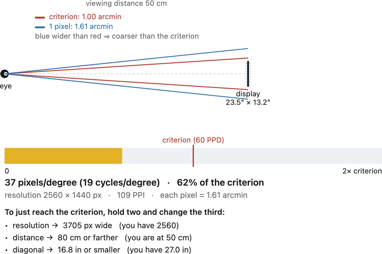
For a rough sizing calculation, take one arcminute per image pixel. This gives a pixel pitch of about $p=d/3438$, or an image density $R\approx3438/d_{\rm in}$ pixels per inch when the distance $d_{\rm in}$ is in inches. It is a design reference, not a universal visibility boundary.
| Viewing situation | Distance | Density at one arcminute per pixel |
|---|---|---|
| Phone | 30 cm | 291 pixels/inch |
| Laptop | 60 cm | 146 pixels/inch |
| Desktop monitor | 70 cm | 125 pixels/inch |
| Television | 3 m | 29 pixels/inch |
The same panel therefore presents a different sampling problem when the viewer leans forward. Extra resolution has more value for a large image inspected closely than for a small image across a room. For a headset, use the angular magnification of its optics; the physical distance from panel to eye alone does not determine pixels per degree.
5.6.3 Sharpening for the display: size and distance⧉
Apply output sharpening after resizing, and judge it at the intended size and viewing distance. A radius measured in pixels has a different angular scale on a small web image and a large print. A few source pixels can become less than one output pixel after reduction; choosing a radius on the final grid controls the edge neighborhood that will actually be displayed.
A useful workflow separates capture, creative, and output sharpening. Capture sharpening compensates for some capture softness within the information recorded by the lens and sensor. Creative sharpening directs attention to selected features, such as eyes or texture. Output sharpening compensates for the final presentation. They need not all be strong or even necessary. A phone JPEG may already contain substantial sharpening.
Paper and ink spread change edge contrast, so a matte print can require different settings from a glossy print or a screen. A distant poster can tolerate halos that would be objectionable in a handheld photograph. A 100% monitor view is useful for diagnosing artifacts, but it represents the final viewing situation only if its scale and distance match the output.
Inspect smooth skin, textured regions and a strong edge; the setting that makes one look crisp may damage another. Use a small test print to check whether fine contrast survives on the chosen medium. Repeated sharpening can exaggerate compression artifacts and produce bright and dark rims. Sharpening cannot restore an out-of-focus eye merely by strengthening its edges.
Reflected ambient light raises the visible black level. Prepare and judge the image under its intended viewing conditions; a panel specification alone does not describe the contrast the viewer will see.
5.6.4 Light level viewing conditions⧉
Keep editing illumination reasonably stable, and avoid reflections across the screen. A display set much brighter than the intended print illumination can encourage an edit that prints too dark. Ambient reflections raise the apparent black level and can hide shadow distinctions even when a panel has low emitted black.
That is why a display's contrast looks very different on a spec sheet than in a living room. Rough orders of magnitude for on-screen contrast, brightest reproducible over darkest, illustrate the gap; measured values vary widely by model, setting and room:
| Display | In a dark, calibrated room | Under ordinary room light |
|---|---|---|
| Reflective print | about 100:1 glossy, 50:1 matte | about 30 to 50:1 |
| Standard LCD | about 1,000 to 4,000:1 | about 100 to 200:1 |
| Local-dimming LCD | about 10,000 to 100,000:1 | about 1,000:1 |
| OLED | very high, with pixels that switch off | about 1,000 to 5,000:1, set by reflections |
| Home projector | about 1,000 to 2,000:1 | about 50:1 |
A phone is held at about 30 cm and seen anywhere from a dark room to direct sun; an editing monitor sits at half a meter to a meter in controlled light; a television is several meters away and often adds its own processing (motion interpolation, local dimming, sharpening). Prepare the photograph for the display and room it will actually meet.
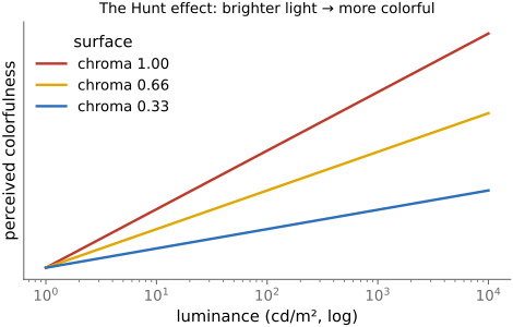
Colorfulness and contrast depend on adaptation and surround. The Hunt effect is one reason the same color measurements need not produce the same appearance at different luminances Fairchild, Color Appearance Models. It does not justify an arbitrary gamma adjustment.
An electro-optical transfer function (EOTF) maps encoded values to emitted display light. The complete scene-to-display mapping also includes capture encoding and rendering. ITU-R BT.1886 specifies a reference display EOTF; its exponent is not an interchangeable end-to-end system gamma. Use the appropriate profile and output transform rather than substituting one exponent for the pipeline. Chapter 4.3, Encoding: linear, gamma or log develops these distinctions.
5.6.5 Viewing position and perspective⧉
Look at the same portrait from directly in front of the print and from an oblique position. The retinal projection changes, yet the face often remains recognizable and reasonably shaped. That tolerance is useful, but incomplete. It does not make every extreme wide-angle face acceptable.
Keep important faces away from the edge of a very wide rectilinear frame when possible, and judge a large reproduction from its likely viewing positions. The demonstration and competing explanations are collected in Perspective distortion and its correction#Robustness of perspective to the viewer's viewpoint.
Recap: big lessons of this chapter
Reflected ambient light raises the visible black level. Prepare and judge the image under its intended viewing conditions; a panel specification alone does not describe the contrast the viewer will see.