22.10 Glare suppression⧉
Every air–glass surface in a lens is a tiny partial mirror. We spend the whole rest of this part treating lens surfaces as things that refract (bend the light on its way to forming the image) but at each uncoated surface a few percent of the light does not refract through; it reflects back. Most of that reflected light eventually leaves the lens harmlessly, but some of it bounces a second time off another surface and heads forward again, now traveling at the wrong angle, and lands on the sensor as light that does not belong to any scene point's image. Multiply that by the dozens of surfaces in a modern lens and you have a real problem: a bright source in or near the frame can paint a chain of bright blobs across the picture, and even an ordinary scene loses contrast to a faint wash of misdirected light.
Be precise about the distinction from the last chapter, because both defects look like "haze" in a photo and both, as we will see, can be attacked with the same deconvolution tool. An aberration takes the light that should form a given image point and misplaces it nearby: the energy is still the image's own light, just blurred. Glare is different in kind: it is light that has taken an illegitimate path (an extra reflection, a scatter off a mount) so that energy from a bright part of the scene (often a part outside the frame entirely) is sprayed across other parts of the image. Aberration blurs a point into a slightly larger point; glare takes a bright source and smears a faint copy of it, or a structureless veil, over everything else.
First we catalog where stray light comes from and the three faces it shows: discrete ghosts, streaky flare, and contrast-killing veiling glare, and we count the reflections to see why a many-element lens makes the problem explode. Then we take the hardware cures in turn: anti-reflection coatings, the thin-film-interference trick that made multi-element lenses possible in the first place; and the blunter geometric tools (the lens hood, internal baffles, and blackened edges) that simply stop unwanted light from getting in. Finally we turn to computational suppression: modeling veiling glare as a broad PSF and deconvolving or subtracting it, dehaze-style contrast recovery, and learned removal of lens-specific flare.
22.10.1 Where stray light comes from: flare, ghosting, veiling glare⧉
Start with the single fact that drives everything in this chapter: at every air–glass interface, some light reflects. How much is given by the Fresnel equation for reflectance at normal incidence,
where $n_1$ and $n_2$ are the refractive indices on the two sides of the surface. For an ordinary air-to-glass interface, $n_1 = 1$ (air) and $n_2 \approx 1.5$ (a typical crown glass), so
about 4% per surface. That number is small but not negligible, and it drives the whole problem. The other 96% refracts through and forms the image; the 4% reflects back into the lens and can create artifacts.
Ghosts. Consider a strong light source (the sun, a streetlamp, a bright reflection) somewhere in or near the frame. Its rays enter the lens and most of the light proceeds normally toward the sensor. But suppose a ray reflects off one surface (losing 96%, keeping 4%), travels back, then reflects again off a second surface (keeping 4% of that), and now heads forward toward the sensor a second time. This doubly-reflected beam has lost the vast majority of its energy (it carries roughly $0.04 \times 0.04 = 0.0016$, less than two-tenths of one percent of the source) but if the source is very bright, that residue is still visibly bright. And because it has traversed the optics along a bent path, it does not focus where the source's real image is. Instead it forms a ghost: a discrete, usually defocused bright blob, frequently shaped like the aperture (because the out-of-focus image of a bright point takes the shape of the diaphragm, recall the bokeh discussion of Depth of field), and typically strung out along the line from the source through the center of the frame, often mirrored to the opposite side. A whole chain of ghosts appears because there are many pairs of surfaces, each pair producing its own double-reflection at its own position. (Figure 22.1.13)
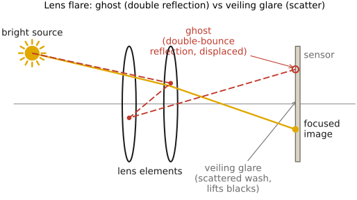
Flare. When the bright source is just outside the frame, its light still enters the front of the lens at a steep angle and reflects or scatters inside the barrel without forming a clean ghost. The result is streaks, arcs, and a generally washed-out region spilling in from the side where the source sits. This is what photographers loosely call flare: the splashy, often colorful artifact you get shooting toward a light just off the edge of the picture. (Some lens designs, the anamorphic optics of Special optics among them, flare in such a characteristic way that the look is now imitated on purpose.)
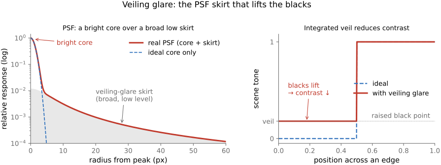
Veiling glare. Not every stray ray forms a recognizable ghost or streak. Most of the misdirected light (the countless weak reflections off every surface, plus scatter off the diaphragm blades, the barrel walls, dust, and microscopic imperfections in the glass) does not concentrate anywhere. It just spreads, more or less uniformly, a thin layer of light over the whole image. This is veiling glare: a low-frequency wash that lifts the blacks and crushes the contrast of the picture. It is the most damaging form of glare precisely because it is invisible as an artifact (there is no obvious blob to point at) yet it quietly robs the image of its deep tones. A shadow that should be black instead reads as dark gray; a scene shot into backlight looks flat and milky. Veiling glare is worst when a bright source sits just outside the frame (so the hood, below, is the first defense) or when you shoot directly into the sun.
Why compound lenses make it worse. Here is the part that ties back to Compound lenses and explains why coatings are not optional but mandatory. The ghost-producing mechanism needs a pair of surfaces: light reflects off one, then off another. If a lens has $N$ air–glass surfaces, the number of distinct surface pairs that can produce a double-reflection ghost is
The count of candidate two-reflection paths grows quadratically; many are blocked or too weak or defocused to appear as separate visible ghosts. A simple triplet has six surfaces: fifteen pairs. A modern fast zoom can have thirty or forty surfaces, which is hundreds of potential ghost paths, and on top of that the cumulative veiling glare grows with the number of surfaces too. Worse, recall from Compound lenses that the T-stop already penalizes a lens for its transmittance loss $\tau$: with 4% lost to reflection at each of, say, thirty surfaces, an uncoated lens would transmit only $0.96^{30} \approx 0.29$: under a third of the light would reach the sensor, and the remaining light would be reflected away, absorbed, or contribute to stray paths. Only a fraction becomes recorded glare. Such losses and ghosts strongly constrain complex uncoated designs. This is the problem that coatings solve, and the entire era of complex, high-element-count photographic lenses was made possible by the coating.
22.10.2 Hardware suppression⧉
The hardware cures attack glare at two different stages. The coating reduces the reflection at each surface, so less stray light is generated in the first place. The hood and baffles are geometric: they prevent off-axis light from ever entering the system, so it cannot scatter. First, coatings.
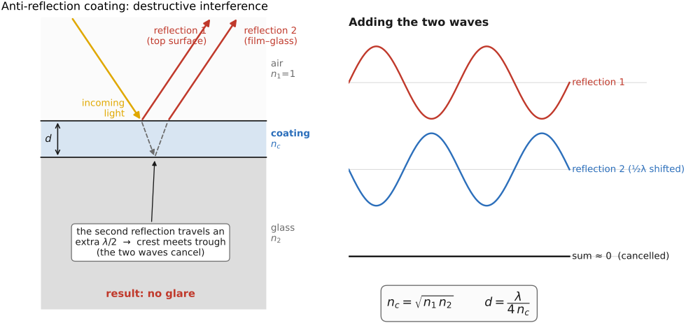
Anti-reflection (AR) coatings. The reflection at a single surface comes from the abrupt jump in refractive index from $n_1$ to $n_2$. The idea of an anti-reflection (AR) coating is to deposit a thin transparent film on the glass so that the light now meets two closely-spaced interfaces (air-to-film and film-to-glass) and to arrange for the two faint reflections from those interfaces to cancel each other by destructive interference. Two conditions make the cancellation as complete as possible.
The first condition is on the film's thickness. The reflection off the film's front face and the reflection off its back face travel paths that differ by twice the film thickness (down and back up). For the two reflected waves to arrive exactly out of phase (crest meeting trough, so they subtract), that extra round-trip path should be half a wavelength. The film thickness must therefore be a quarter of a wavelength (down a quarter and back up a quarter makes a half-wavelength round trip), measured inside the film:
where $n_c$ is the film's index and $\lambda$ the wavelength in vacuum. This is the famous quarter-wave condition.
The second condition is on the film's index $n_c$, and it makes the two reflections not just opposite in phase but equal in amplitude, so they cancel completely. The reflection at the air–film interface has reflectance $((n_1 - n_c)/(n_1 + n_c))^2$ and the reflection at the film–glass interface has reflectance $((n_c - n_2)/(n_c + n_2))^2$. Setting these equal works out to the condition that the coating index should be the geometric mean of the indices it sits between:
For an air-to-glass surface ($n_1 = 1$, $n_2 \approx 1.5$) this asks for $n_c = \sqrt{1.5} \approx 1.22$. Real coating materials only approximate this (magnesium fluoride, the classic single-layer coating, has $n_c \approx 1.38$, a bit high) but even an imperfect match drops the per-surface reflection from ~4% to around 1–1.5%, a large win.
The catch with a single quarter-wave layer is that both conditions hold exactly only at one wavelength (the one $\lambda$ that makes the film a true quarter-wave) and one angle of incidence; away from that wavelength the cancellation is partial, which is why a single-coated surface reflects a faint residual color: the coating is tuned to null green, say, and leaks a little blue and red, giving the surface a purple sheen. The fix is a multi-layer coating: a stack of several films of alternating index, whose combined interference can be engineered to suppress reflection across the whole visible band and over a range of angles. This is the colored, oily sheen you see on the front of a modern lens: each visible tint is the small residual reflection the stack could not quite kill. Multi-layer coatings push the per-surface reflectance down to ~0.1–0.5%, and that is the number that made the thirty-surface zoom practical: at 0.3% per surface, thirty surfaces transmit $0.997^{30} \approx 0.91$ instead of 0.29, and the glare budget shrinks by more than an order of magnitude. (The detailed multilayer theory belongs to the FUNDAMENTALS lens-coating history; here we have done the one-layer physics and named the multilayer generalization. The history of who first discovered coatings, and how the method spread during and after the war, is in the sidebar below.) (Figure 22.10.1)
The single most consequential trick in this chapter has a tangled history, a case study in how an industrial secret escapes. The vacuum-deposited quarter-wave coating was invented in 1935 by Alexander Smakula, a Ukrainian-born physicist at Carl Zeiss in Jena (German patent DE 685767, "a method for increasing the light transmittance of optical parts"). Zeiss and the German military grasped at once what it was worth (a coated gunsight or pair of binoculars gathers more light and, just as important, throws fewer tell-tale reflections back at the enemy) and the invention was promptly classified. The patent was withheld from publication until 1944, and through the late 1930s Zeiss ran more than a dozen coating chambers whose output went only to military optics, stamped with a small red "T" (for Transparenz, transmission, the ancestor of today's T\* multicoating).
It was never, however, a uniquely German idea. John Strong at Caltech published an independent re-invention in 1936 (he evaporated a fluoride film onto a Leica's lenses, probably the first coated camera lens outside Germany) and Cartwright and Turner at MIT were coating optics by 1938; Katharine Blodgett at General Electric demonstrated a different (and fragile) anti-reflection film the same year. So when World War II ended, two things happened at once. First, the patent monopoly evaporated: among the spoils of victory, Allied teams seized and microfilmed some 145,000 German patent files, and the U.S. Office of Alien Property vested tens of thousands of German patents (the 1946 London Agreement on German-owned patents formalized the principle) so that German optical know-how, coatings included, became freely available to Allied industry with no royalty owed. Second, Zeiss itself was torn in two: as the war closed, American forces evacuated roughly a hundred senior Zeiss scientists and managers westward from Jena to Oberkochen in the U.S. zone, days before the Soviets took Thuringia and dismantled most of the Jena works as reparations. For the next four decades a Western Zeiss (Oberkochen) and an Eastern VEB Carl Zeiss Jena both claimed the name, fighting a trademark war settled only in 1971 and ended only by German reunification in 1991. The lesson for the history of optics is the plain one: the coating spread across the world not because a single patent fell, but because the idea had already been discovered in the open more than once: the war merely made certain of it.
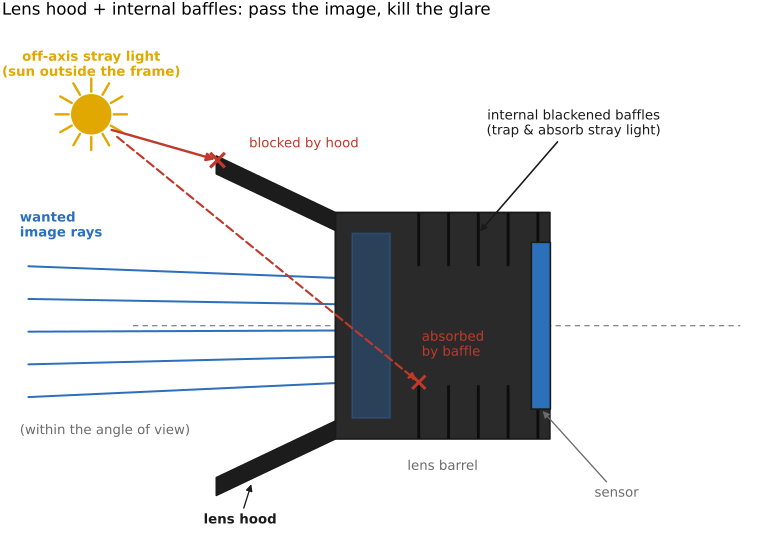
Lens hood. The simplest, cheapest, and often most effective anti-flare device does not touch the glass at all: it is a tube or petal of black plastic on the front of the lens. A lens hood blocks light from sources outside the frame from ever striking the front element. Since much of the worst flare and veiling glare comes from a bright source just off the edge of the picture, intercepting that light before it enters the lens removes the artifact at its origin. If the stray light never enters the lens, it cannot reflect or scatter inside it. The hood is shaped (the "petal" or "tulip" cutouts) so that it shades as deeply as possible without intruding into the rectangular field of view it must leave unobstructed. (Figure 22.10.3)
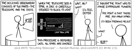
Internal baffles, blackened edges, and barrel paint. Inside the barrel, the remaining defense is to make every surface that is not supposed to carry image light as black and non-reflective as possible, and to physically block grazing rays. Internal baffles are rings and ridges machined into the barrel that stop a ray skimming down the inside wall from reaching the sensor; the edges of the glass elements are painted black so light cannot enter the glass from the side and pipe through it; and the whole inner barrel is finished with deep-black, often textured anti-reflective paint (and increasingly engineered ultra-black coatings). All of this matters most where the bright source is overwhelmingly stronger than the target, most dramatically in telescopes, and above all space telescopes, which must image impossibly faint objects with the unshielded sun or the bright limb of the Earth just out of the field. There, elaborate baffle tubes and light traps are as much a part of the optical design as the mirrors themselves (cross-ref Special optics, telescopes and reflecting systems). Blocking an overwhelming source so that a faint neighbor becomes visible is the coronagraph's job. A joke version of the same idea appears in (Figure 22.10.2). (Figure 22.10.3)
22.10.3 Computational deflare and glare deconvolution⧉
Hardware leaves a residual level of glare: even a perfectly coated, hooded, baffled lens has some residual reflectance and scatter, and when you shoot straight into a bright source there is no hood angle that helps. The same optics-plus-software division applies here: reduce glare optically, then remove the remainder in software. Veiling glare can be modeled with the same PSF framework used for blur, so calibrated inverse methods can help, with additional difficulties from spatial variation, sources outside the frame, clipping, and photon noise.
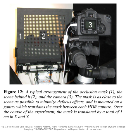
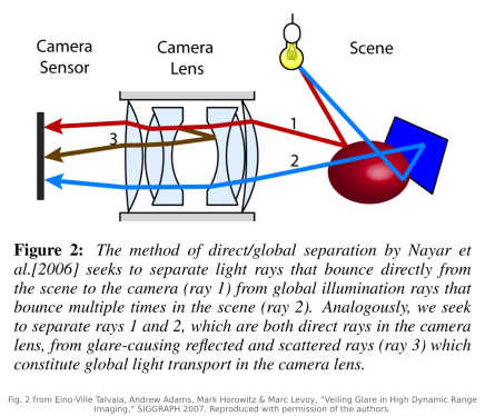
Glare as a broad PSF. A useful approximation retains the direct image as well as the weak broad tail: $y\approx(1-\alpha)x+\alpha(k_g*x)+g+n$, where $k_g$ is a normalized broad glare kernel, $\alpha$ the fraction assigned to it, $g$ discrete ghosts or contributions from outside the modeled field, and $n$ noise. This convolution assumes approximately shift-invariant glare; a general calibration uses a space-varying transport operator. Where an aberration's PSF is a small, tight blur (it spreads a point a few pixels), the glare PSF is broad and shallow: a tiny fraction of each bright point's light is spread far and wide across the whole frame. That long, low tail is exactly the veiling wash. If you can measure this glare spread function (for instance by photographing a single bright point in a dark surround and recording how its light leaks across the rest of the sensor), then you can estimate the scattered component and solve for the direct image. Subtraction requires an estimate of both the spread function and the source image; subtracting the mean glare cannot remove its shot noise or recover clipped values. A particularly direct way to measure the glare is to place a structured occlusion mask between the scene and camera and acquire a sequence at different mask positions: the mask lets one separate the direct, image-forming light (rays that pass cleanly to their proper pixel) from the global veiling component (rays scattered inside the lens onto pixels where they do not belong), so direct and indirect transport can be separated without fitting one parametric glare kernel. Blocking bright contributions during capture also reduces their photon noise, which simple after-the-fact subtraction cannot do (Talvala et al. 2007). (Figure 22.10.4) Raskar and colleagues moved the mask into the camera, close to the sensor, where it samples the 4-D light field: the rays reaching a pixel from different parts of the aperture are recorded separately, glare shows up as outliers among them, and rejecting the outliers reduces glare in a single photograph, at a cost in spatial resolution Raskar et al. 2008 (glare-aware photography). This is the same calibrated, non-blind deconvolution of Aberrations correction (Wiener and regularized inverse filters), pointed at stray light rather than at the lens's own blur. The discrete ghosts, being lens-specific and source-position-specific, are harder to model as a single kernel and are usually handled separately (often by learned methods, below). (Figure 22.10.5)
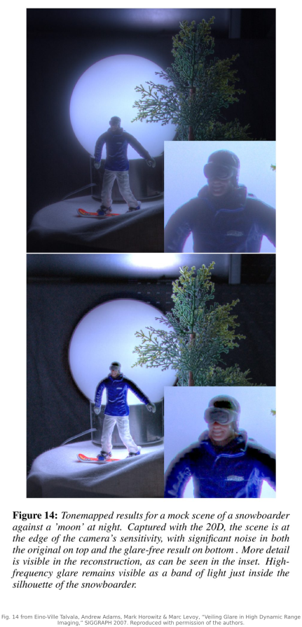
Dehaze-style recovery and learned deflaring. A second, more model-free route treats veiling glare like atmospheric haze: both are a low-frequency additive wash that lifts the blacks, so the dehazing contrast-recovery methods (cross-ref dehazing) can suggest useful priors, but the forward models differ: atmospheric haze includes depth-dependent attenuation and airlight, whereas camera glare redistributes light within the imaging system. Contrast recovery alone is not a calibrated estimate of scene radiance. For the discrete artifacts (the chain of ghosts and the streaky flare) the pattern depends intimately on the particular lens, the source position, and even the aperture setting, which makes a hand-built model brittle; here learned flare- and ghost-removal networks have become the practical tool. Pairs of flared and clean images are hard to photograph, so they are made: Wu and colleagues added captured and simulated flare to clean photographs Wu et al. 2021 (flare removal), and the Flare7K dataset provides 7,000 synthesized nighttime flare patterns for the same purpose Dai et al. 2022 (Flare7K). Glare suppression matters especially for high-dynamic-range (HDR) capture: when you are trying to measure the faint, dark end of a scene that also contains a very bright source, veiling glare from that source contaminates exactly the dark measurements you care about, so removing it is essential to getting the shadows right (Talvala et al. 2007). Merging more exposures does not help, since every exposure contains the same glare in proportion: McCann and Rizzi found that glare, not the sensor, limits the range a camera can measure McCann & Rizzi 2007, and Chapter 17.1, Dynamic range and multiple-exposure capture works through how much. Measuring and subtracting the glare restores the milky, contrast-robbed shadows to deep blacks (Figure 22.10.6), and doing so before assembling the exposure stack is what lets the recovered HDR image hold real detail in the dark tones next to a bright source (Figure 22.10.7). The full treatment of learned deflaring is forward-referenced to the Advanced part; here it is enough to see that glare, like aberration before it, is another case where moderate optical suppression plus computation works better than either approach alone.