31.2 Light field cameras⧉
A conventional pixel is a sum. The optics chapter made this precise and Chapter 31.1, Light fields 101 turned it into the founding idea of this part: a lens gathers a whole cone of rays from each scene point through its aperture and focuses them onto one sensor location, and the pixel records only their total, the integral over the aperture. The directions the individual rays came from are averaged away the instant the light lands. That average is exactly what determines focus: change which rays land where (refocus, stop down, shift the viewpoint) and you change the picture, but once the shutter closes the choice is frozen. The light field is what you hold if you refuse to take that integral. Keep each ray separately, and you can make those choices afterward. The whole of this part rests on it.
So the engineering question is blunt: a sensor pixel is a bucket that sums photons; how do you get it to record which direction each photon arrived from? You cannot ask a single pixel to report an angle. The trick in every design below is the same: use optics to sort rays by direction onto different pixels before they are summed, so that the angular information ends up spread across space on the sensor, where ordinary pixels can record it. Three families do this sorting in three different ways. The lenslet plate and the microlens camera record many ray samples in one exposure, with a main lens in the latter design; the third spreads it across many cameras. We build all three, then show they are the same object captured under opposite constraints.
The light field is the aperture/angle instance of the part's recurring lesson: instead of committing to one focus, one aperture, and one viewpoint at the instant of exposure, record every ray and choose afterward. HDR defers the exposure decision, panorama the viewpoint, focus stacking the focus distance; the light-field camera defers all three at once by capturing the rays themselves. The cameras in this chapter are the hardware that makes the deferral possible; the price is more data and a harder reconstruction, and here also, as we will see, a literal cost in sensor resolution.
31.2.1 Integral photography: Lippmann's fly's-eye plate (1908)⧉
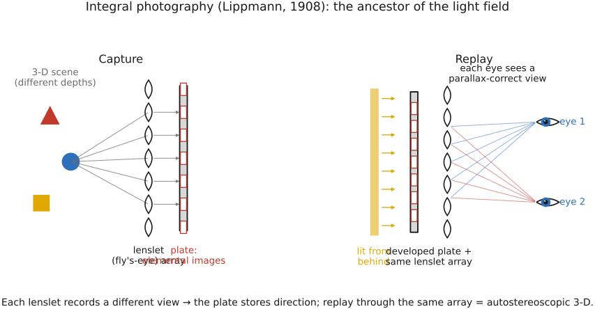
The first light-field camera predates electronics by a century. In 1908 Gabriel Lippmann, the same physicist whose interference-based color process appears in Chapter 4.6, Sensing color: multiplexing strategies, proposed integral photography: photograph the scene not through one lens but through a sheet of many tiny lenses, a fly's-eye array, focused onto a single photographic plate behind it. Each little lens forms its own miniature image of the scene from its own slightly different position on the plate. Lippmann called the goal a "window onto the world," and the optics deliver it almost literally.
The key is what each lenslet records. Because the lenslets sit a few millimeters apart, each one sees the scene from a marginally different vantage, the same parallax you get by moving your head a hair sideways. So under each lenslet the plate stores a tiny picture, called an elemental image, and neighboring elemental images differ in their parallax. A point on a near object lands at a slightly different spot under each lenslet than a point on a far object; the pattern of those shifts across the array is precisely the scene's directional information. In the language of Chapter 31.1, Light fields 101: the lenslet you look through picks the aperture coordinate $(u,v)$, and the pixel under it picks the focal-plane coordinate $(s,t)$, so the plate as a whole is a sampling of $L(u,v,s,t)$, a slice of the light field, recorded on emulsion.
The reason it works is the replay. Develop the plate, lay it back behind the same lenslet sheet, and illuminate it from behind. Each lenslet now re-emits the rays it originally collected, back out in the directions they came in, so the array reconstructs the original ray bundle. Walk past it and the picture shows parallax: near objects shift against far ones, just as in the real scene. This is an autostereoscopic 3-D image: it gives depth to both eyes at once, with no glasses, because each eye, sitting at a different position, intercepts a different set of replayed rays. That replay principle is the direct ancestor of today's lenticular prints and integral-imaging 3-D displays; the same fly's-eye sheet, run forward as a camera and backward as a display, is the seed of both the plenoptic cameras below and the autostereo displays we will return to. (We come back to the display side in the frontiers chapter.)
31.2.2 The plenoptic camera: a microlens array on the sensor⧉
Lippmann's idea, dragged inside a modern camera body, becomes the plenoptic camera, the lineage that runs from Adelson and Wang to Ng's hand-held Lytro. The move is small and exact: take the fly's-eye sheet and place it as a microlens array directly in front of the sensor, just behind the camera's ordinary main lens. The main lens does its usual job and forms an image, but now it forms that image on the plane of the microlenses rather than on the bare sensor.
Here is the geometry that makes it work. Pick one microlens. The main lens has focused a single scene point onto it, so all the rays from that scene point arrive at that one microlens, but they arrive having passed through different parts of the main-lens aperture, so they arrive at different angles. The microlens, being a lens, sorts rays by angle: it takes the cone of rays hitting it and spreads them across the several pixels sitting behind it. Concretely, the microlens images the main-lens aperture onto that little patch of sensor, so behind each microlens you get a tiny picture of the aperture, a sub-image, with a ray's position in the sub-image telling you which part of the aperture it came through.
One constraint makes the whole arrangement tile cleanly: the f-number of the main lens must match the f-number of the microlenses. The sub-image behind each microlens is a picture of the main-lens aperture, so its diameter is set by how fast the main lens is; match the two f-numbers and each sub-image grows to fill its microlens's share of the sensor exactly: no wider (where neighboring sub-images would overlap and scramble the angular samples) and no narrower (where the gaps between sub-images would waste pixels). The matched-f-number design is what lets the sub-images use the sensor efficiently without unacceptable overlap. Circular pupils and lattice geometry can still leave unused regions.
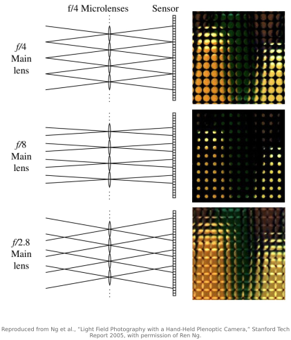
Read that back in light-field terms, because it is the point. One microlens = one spatial sample of the scene; the position of the microlens on the array is the focal-plane coordinate $(s,t)$, sometimes called a macropixel. The pixels under that microlens = the angular samples; a pixel's position within the sub-image is the aperture coordinate $(u,v)$. So a single body, in a single hand-held exposure, lays the full 4-D field $L(u,v,s,t)$ out flat on the sensor: spatial structure across the microlens grid, angular structure within each sub-image. No moving parts, no multiple shots. This is the design Adelson and Wang built in 1992 Adelson & Wang 1992 to compute depth, because the angular samples are tiny stereo views, so disparity gives range, and that Ng et al. revisited in 2005 Ng 2005 for refocusing, packaged as the hand-held camera that became Lytro. Raytrix sells a variant for industrial and microscopy work, and modern arrays are typically laid out on a hexagonal grid, which packs the round microlenses more tightly than a square one. That hexagonal, slightly-rotated lattice is exactly why a raw plenoptic frame is not a usable array: turning the honeycomb of sub-images into the regular 4-D grid $L(u,v,s,t)$ the rest of this part assumes is a decode pipeline in its own right: fit the microlens lattice to sub-pixel accuracy, then resample hex→rectangular, worked out step by step, for the Lytro Illum, in the appendix Chapter 45.23, Reading a Lytro light field.
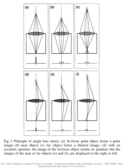
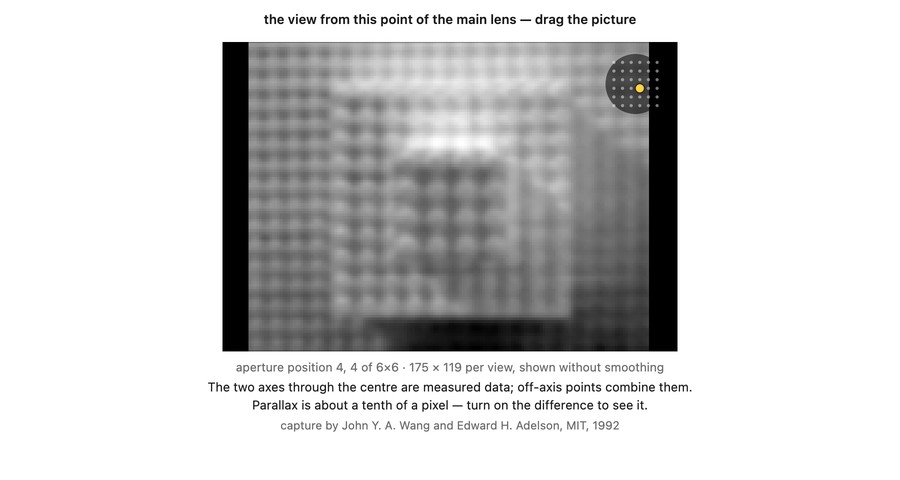
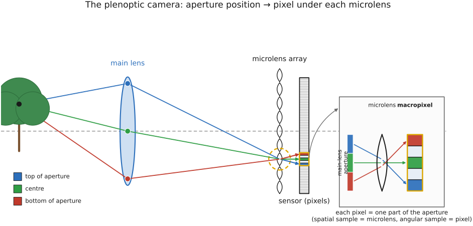
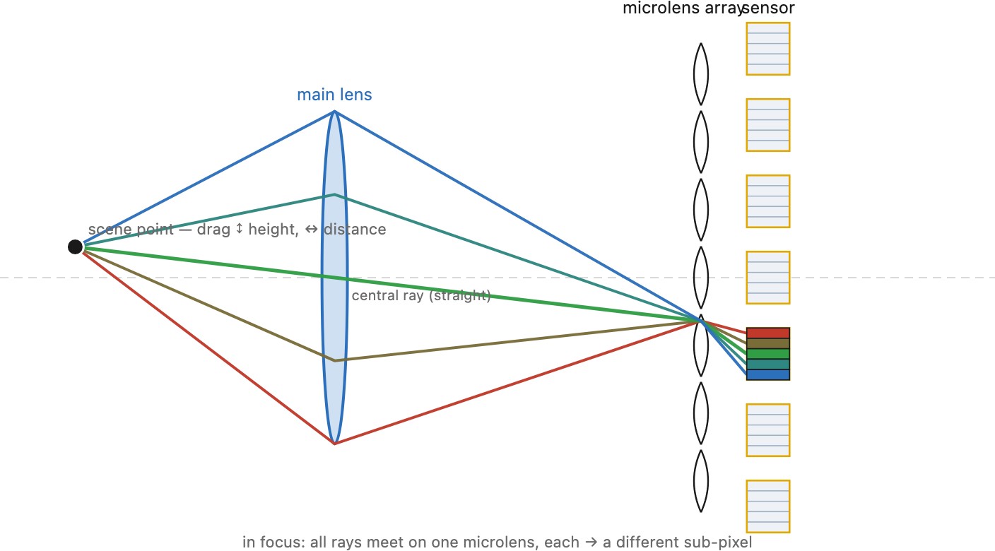
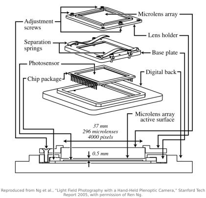
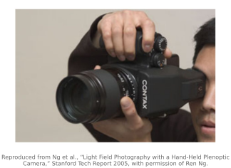
The diagram is idealized; the real thing is a chip. Ng et al. built exactly this in 2005 Ng et al. 2005 as a hand-held camera, a conventional medium-format body with a microlens array bonded a fraction of a millimeter in front of the sensor, the prototype that became Lytro.
There is a tradeoff, and the catch is the central fact about plenoptic cameras: resolution. The angular samples come out of the sensor's pixels. Every pixel you spend recording the angle within a sub-image is a pixel you are not spending on a finer spatial grid. So the naive final image's spatial resolution is set by the number of microlenses, not the number of pixels: a sensor that would make, say, a 16-megapixel ordinary photograph yields, if you just take one pixel per microlens, a light-field image of far fewer spatial samples, because each microlens claims a small block of pixels for its sub-image. You appear to buy fine angular sampling, the ability to refocus and shift viewpoint after the shutter, by paying spatial resolution out of the same fixed pixel budget.
But that accounting is pessimistic: reconstruction can recover much of the apparent loss. The sub-images under neighboring microlenses are not independent; they are shifted views of the same scene, so a smart reconstruction that models the optics and exploits a natural-image prior can recover far more spatial detail than the one-pixel-per-microlens count suggests, pulling much of the "lost" resolution back out of the angular samples (this is the shape-prior / super-resolved rendering developed in Chapter 31.7, Lumigraph and shape priors for sharper light field rendering). So read the resolution law as a statement about the raw trade, not a hard ceiling on what you can compute back. Hold onto it anyway; it is the axis the chapter is built on, and the next design spends the budget the opposite way.
31.2.3 Lytro: the consumer plenoptic camera⧉
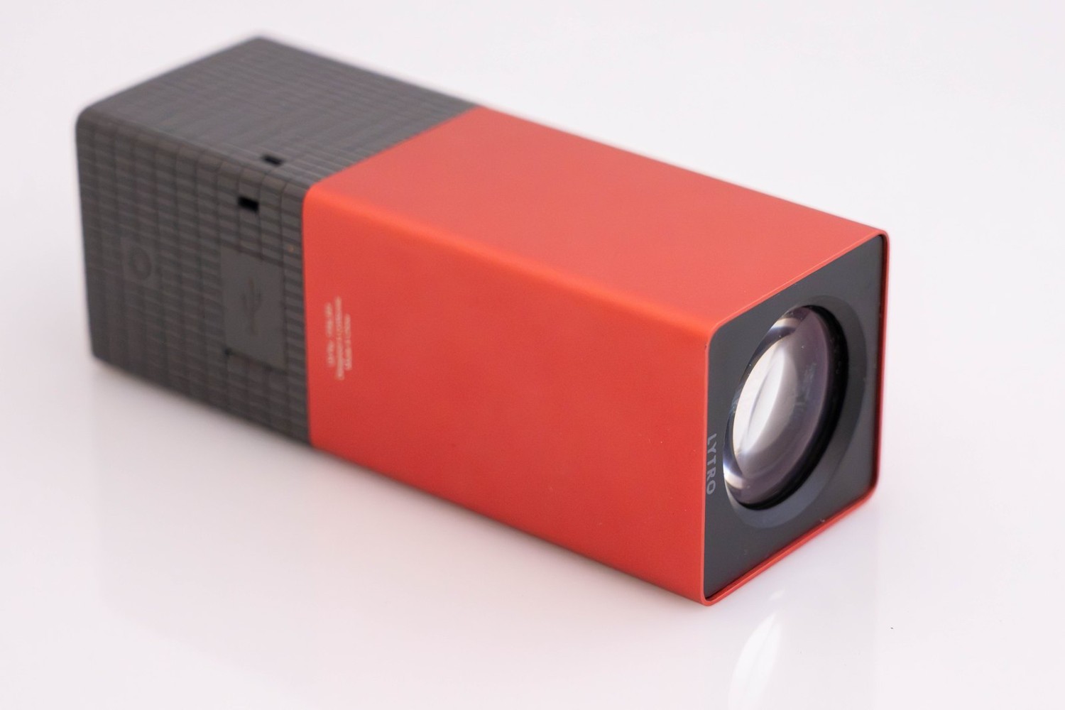
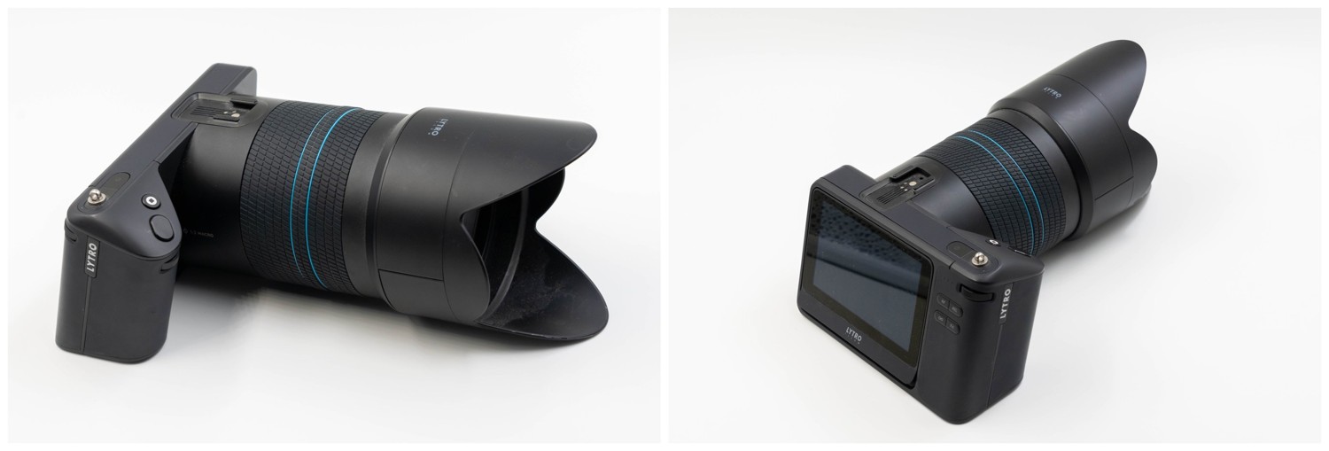
The plenoptic camera left the lab as a product. Lytro, founded on Ren Ng's Stanford thesis, shipped the first consumer light-field cameras: the original Lytro in 2012, a lipstick-shaped body sold on the promise "shoot now, focus later", and the SLR-styled Lytro Illum in 2014. Inside, exactly the design above: a microlens array in front of the sensor records the 4-D field in one hand-held exposure, and software then delivers post-capture refocus, a perspective/viewpoint shift, and a depth map from that single shot.
The two cameras in numbers, and the trade they made. The original Lytro packed an 11-"megaray" sensor (≈11 million photosites) behind its microlens array but delivered only a ≈1-megapixel refocusable "living picture"; the Illum roughly quadrupled everything, with a 40-megaray sensor, a ≈4-megapixel output, and an 8× (≈30–250 mm-equivalent) zoom. Both held a constant f/2 at every focal length. That sounds fast, but both used small sensors, a smaller sensor in the original and a larger one in the Illum, and sensor size changes what "f/2" means for depth of field. Depth of field tracks the 35 mm-equivalent aperture, which is the f-number times the crop factor: for example, an f/2 lens on a camera with a 3× crop factor has roughly the depth of field of f/6 on full frame at matched framing, viewpoint and output viewing conditions. Use the active image dimensions, not the sensor’s nominal inch designation, to calculate the crop factor. Small sensors often give greater depth of field for matched framing and output criteria, but that is not the mechanism of light-field refocusing. Angular separation retains rays that would form a defocus blur if summed directly. Their resampling can refocus within the capture’s supported range; it cannot synthesize arbitrary apertures or recover unmeasured detail.
The cost is the plenoptic camera's defining trade: spatial resolution for angular resolution. Each microlens contributes one spatial sample and, beneath it, on the order of ~10×10 ≈ 100 angular samples (the sub-aperture views). So the naïve spatial resolution is the number of microlenses, not photosites, only about 0.1 megapixel for the original and a few tenths of a megapixel for the Illum, a small fraction of the 11- and 40-megaray sensors feeding them. The cameras nonetheless output ~1 and ~4 megapixels because of light-field superresolution: reconstructing the refocused (or all-in-focus) image pools detail from the many angular views, using reconstruction that can exploit sub-view shifts and scene structure (see Chapter 31.7, Lumigraph and shape priors for sharper light field rendering for related geometry-aware rendering ideas), recovering several times the one-pixel-per-microlens floor. It never reaches the sensor's raw pixel count, though, which is exactly why plenoptic still cameras never matched ordinary cameras on sharpness, and why Lytro ultimately turned away from consumer photography.
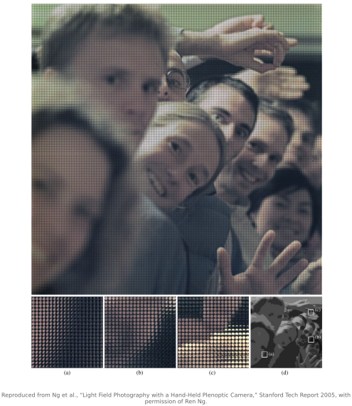
Here is what one of these captures actually is on the silicon. Figure 31.2.12 is a real raw frame off the author's own Lytro Illum, and hovering over the interactive version below lets you find the microlens patterns yourself.
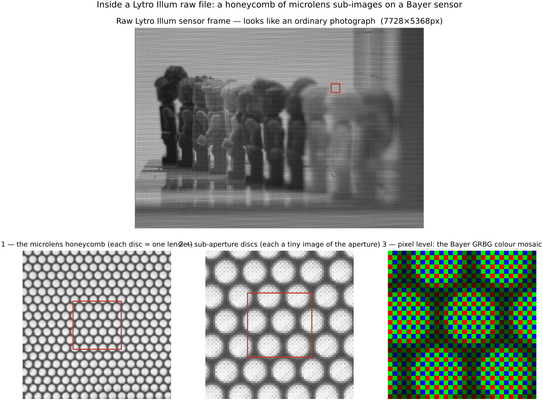
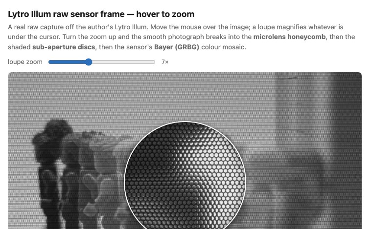
It is also the cleanest real-world case study of the resolution law we just stated. The Illum's sensor captures on the order of 40 megarays, but an exported picture has far fewer independent spatial measurements. Export dimensions and actual resolved detail are different quantities; the roughly four-megapixel Illum output cited above should not be confused with a smaller web-viewer rendering. That, together with large file sizes and a fairly thin set of must-have uses (most photographs do not, in the end, need refocusing), is why the product did not survive commercially: Lytro pivoted to light-field video and VR and shut down in 2018. The ideas did not die with it. Raytrix still sells plenoptic cameras for industrial and microscopy work, and the smallest light field, the dual-pixel sensor, is used in many phone cameras (→ Chapter 22.9, Autofocus). And the decoded Lytro Illum captures are what drive this book's interactive light-field viewer; the exact pipeline that turns a raw .lfr into a usable 4-D array is the appendix Chapter 45.23, Reading a Lytro light field.
31.2.4 Commercial light-field cameras beyond Lytro⧉
Lytro was the loud consumer story, and its failure is often read as the failure of light-field cameras in general. That reading is wrong. While Lytro chased the mass market and lost, a quieter industry grew up around the same optics for jobs where the light field's main use, a 3-D measurement from a single shot with no moving parts, is worth far more than sharpness. The survivors are almost all industrial and scientific.
The central one is Raytrix, the German company (Christian Perwass and Lennart Wietzke) that has sold plenoptic cameras since 2010, before the first Lytro shipped, and still does. Its design is a deliberate variation on Ng's that is worth understanding, because it spends the pixel budget differently. Ng's camera focuses the main lens onto the microlens plane, so each microlens sees a single scene point and its pixels sample only the aperture; this is the unfocused or plenoptic 1.0 design, and the simplest spatial grid has one sample per microlens, before reconstruction from multiple angular views. Raytrix instead uses the focused plenoptic (plenoptic 2.0) design of Lumsdaine and Georgiev (Lumsdaine & Georgiev 2009 (focused plenoptic)): the microlens array is placed so that each microlens relays a small, in-focus patch of the main image, so every microlens records a little picture of the scene rather than of the aperture. This trades some angular sampling back for spatial resolution, and it is why Raytrix can quote effective resolutions that are a much larger fraction of the raw sensor than Lytro's were. Raytrix pushes the idea further with a multi-focus array that interleaves microlenses of three different focal lengths, each covering a different range of object depths, so the working depth of field is stretched well beyond what a single microlens focal length would give (Perwass & Wietzke 2012 (Raytrix)). The products are unmistakably instruments, not consumer toys: bodies named by ray count (the R42, for example, lists 41.3 million sensor pixels, about 10 effective megapixels and up to 7 fps), a C- or F-mount that takes ordinary machine-vision lenses, and software that outputs a calibrated depth map and a metric point cloud. They are sold for inline inspection, robotics, particle-image velocimetry, and light-field microscopy, where a single exposure captures a focal stack that would otherwise need a through-focus scan.
Other ventures explored different ways of allocating the sensor and optical path:
- Pelican Imaging took the array route rather than the microlens route, building a compact grid of tiny fixed cameras meant to sit in a phone, with Nokia among its backers. It never shipped in a mainstream handset and its assets were absorbed (into Xperi/Tessera) around 2016, but it prefigured exactly the multi-camera depth-and-refocus pipeline that phones now run with two or three modules (Part 32, Multi-aperture imaging).
- K|Lens, another German effort, tried to bring the light field back to ordinary cameras in 2021 with a lens-shaped adapter: a kaleidoscopic mirror tunnel inside the barrel splits the aperture into nine sub-images tiled onto a normal camera's sensor, so any mirrorless body becomes a coarse light-field camera. The Kickstarter was canceled in early 2022 and the company redirected the same optics to industrial inspection, the same consumer-to-industrial drift as everyone else.
- Rebellion Photonics and d'Optron occupy the narrowest niches: Rebellion builds hyperspectral gas-imaging systems that see gas, imaging methane and other leaks as a visible plume for oil-and-gas safety, and d'Optron sells plenoptic optics for microscopy. Earlier, Adobe (again Todor Georgiev) built research prototypes, including a plenoptic lens with an array of nineteen sub-lenses in front of a conventional camera, exploring the same focused-plenoptic tradeoff Raytrix later commercialized.
The pattern across all of them is the lesson Lytro taught the hard way. As a replacement for the everyday camera the light field loses, because most photographs never needed refocusing and the resolution tax is real. As a measurement instrument, single-shot 3-D from one lens with no sequential scan or separate-camera rig, though internal geometric calibration remains essential, it is genuinely valuable, and that is where the commercial cameras that survived actually live. The largest deployment of all, though, wears none of these names: the dual-pixel sensor, the smallest possible light field with just two angular samples per photosite, ships in many phone cameras, where it drives autofocus and portrait-mode depth (→ Chapter 22.9, Autofocus).
31.2.5 Camera arrays: a grid of full cameras⧉
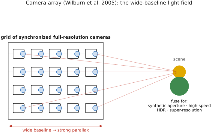
The third family refuses the tradeoff by throwing hardware at it. Instead of subdividing one sensor's pixels into angular samples, a camera array uses many whole cameras, a grid of synchronized, full-resolution cameras spread out in space, each capturing the scene from its own position. Each camera is one angular sample $(u,v)$; the array of viewpoints is the aperture sampling. Wilburn et al. built the canonical instrument in 2005 Wilburn et al. 2005, the Stanford multi-camera array, a wall of inexpensive video cameras, synchronized to the microsecond and calibrated together, streaming in parallel. Because every camera is full-resolution, each angular view is a full image; nothing is paid out of spatial resolution.
The cost reappears in two other places. First, form factor: this is a rig, not a pocket camera. It is a frame of cameras with cabling, synchronization, and calibration, the opposite of the single hand-held body. Second, the angular samples are now coarse and far apart: the cameras sit centimeters to meters from one another, so the array samples direction sparsely over a wide baseline. That wide baseline is also a capability, because a synthetic aperture as wide as the whole rig produces parallax and depth effects no single lens could (we exploit exactly this in Chapter 31.4, Refocusing and synthetic aperture to see through occluders). The same capture idea has been built in several other rigs: motorized gantries that move one camera to thousands of positions in sequence (trading time for cameras), robotic arms that do the same under program control, and Jason Yang's flatbed-scanner camera, which slides a sensor across an image plane to sweep out the views. (Yang also built an MIT cousin of the Stanford array.) These differ in mechanics but share the principle: sample the aperture by moving the camera, not by subdividing pixels.
31.2.6 The spatial↔angular tradeoff⧉
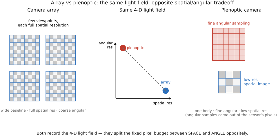
Now the point the chapter has been building toward. The plenoptic camera and the camera array look like completely different machines, one a single body with a microlens chip and the other a wall of cameras, but they capture the same 4-D light field. They differ only in how they spend a fixed pixel budget between the two halves of that field: the spatial axis $(s,t)$ and the angular axis $(u,v)$. And they spend it in exactly opposite ways.
The plenoptic camera buys fine angular sampling at the cost of spatial resolution. Its angular samples come out of the sensor's own pixels, the block of pixels under each microlens, so dense angular sampling means few spatial samples, all on one sensor, in one exposure. The array does the reverse: it keeps every view full-resolution and pays in angular coarseness, sampling direction sparsely with a handful of whole cameras spread over a wide baseline. At fixed total sample count there is a sampling-budget tradeoff. Arrays can add sensors and hardware bandwidth rather than accept the same one-sensor budget. State it plainly:
- Plenoptic: one body, one exposure, dense angular sampling, low spatial resolution, a tiny baseline (the rays all pass through one small main-lens aperture, so the angular spread, and the parallax, is small).
- Array: many bodies, a rig, coarse angular sampling, full spatial resolution per view, a wide baseline (strong parallax, a genuinely large synthetic aperture).
So two practical axes organize the whole space. The first is spatial-vs-angular resolution, where you spend the pixel budget. The second is form factor vs baseline: a pocketable single body with a millimeter-scale aperture at one extreme, a room-sized rig with a meter-scale baseline at the other. A modern multi-camera phone, which we take up in Part 32, Multi-aperture imaging, is a coarse few-camera array squeezed into a body; a Lytro is the dense single-sensor extreme. Everything between them is a choice on these two axes, and there is no design that wins both. That is why "I want a light-field camera" remains a live wish rather than a solved product, a thread we pick up in the frontiers chapter.
31.2.7 Two strategies, and why arrays and microlenses are dual⧉
There is a cleaner way to see why these two machines are not really rivals but mirror images. The light field is four-dimensional, two spatial coordinates $(s,t)$ and two angular $(u,v)$, and any real rig has to lay all four out onto a 2-D sensor (and across time). The choice that defines an acquisition strategy is which of the four dimensions you organize the capture around. In other words, which you put on the outside and which on the inside.
- A camera array organizes around the angular axis: the outer structure is the grid of viewpoints $(u,v)$, one whole camera per direction, and inside each camera sits a full spatial image $(s,t)$. On the sensor you get full pictures laid side by side, one per viewpoint.
- A plenoptic (microlens) camera organizes around the spatial axis: the outer structure is the grid of microlenses $(s,t)$, one macropixel per scene location, and inside each microlens sits the little angular image $(u,v)$ of the aperture. On the sensor you get tiny sub-images laid side by side, one per spatial sample.
So the two designs hold the same 4-D array $L[s,t,u,v]$ and differ only in which index is the outer loop and which is the inner loop. For calibrated samples on equivalent grids, their storage layouts are related by a transpose or reshape (swap the $(s,t)$ and $(u,v)$ blocks). Actual cameras differ in sampling locations, blur, vignetting, and baseline; a reshape alone does not make the measurements equivalent. An array is "angular-outer, spatial-inner"; a plenoptic camera is "spatial-outer, angular-inner." Read the sensor of one and re-tile it and you have the layout of the other. This duality is why the whole design space (gantries, microlens chips, mask-based captures, → Chapter 31.3, Other light field acquisition setups) is really one space: every light-field camera is a choice of how to fold the four dimensions onto two, and the array and the microlens array are simply its two extreme foldings.
Recap: big lessons of this chapter
The light field is the aperture/angle instance of the part's recurring lesson: instead of committing to one focus, one aperture, and one viewpoint at the instant of exposure, record every ray and choose afterward. HDR defers the exposure decision, panorama the viewpoint, focus stacking the focus distance; the light-field camera defers all three at once by capturing the rays themselves. The cameras in this chapter are the hardware that makes the deferral possible; the price is more data and a harder reconstruction, and here also, as we will see, a literal cost in sensor resolution.