33.3 Coded aperture⧉
A normal photograph throws away its own depth. The lens collapses a three-dimensional scene onto a flat sensor, and one optical cue to distance is defocus blur: things at the focus distance are sharp, things nearer or farther are smeared into a disc whose size grows with how far out of focus they are. You can see the depth (your eye reads the blur instantly) but you cannot easily recover it, and worse, the blur has wrecked the parts of the picture it touched. Coded aperture is one mask, dropped into the lens, that turns both of those liabilities into assets: a single coded shot can support joint depth estimation and deblurring, with accuracy limited by texture, noise, the depth range, and visibility. We met that headline already, as the hopeful coda to Chapter 16.4, Blind deblurring. The idea is to make the forward operator well behaved instead of fighting a bad one. This chapter is how the mask actually does it.
The whole idea turns on a single comparison: the defocus blur of a clear aperture is a bad linear operator, and the defocus blur of a coded aperture is a good one. So we start by being precise about what "bad" means.
33.3.1 The bad forward operator of a clear aperture⧉
Defocus is, locally, a convolution: an out-of-focus point of light images not to a point but to a little patch, the point-spread function, or PSF, and the blurred image is the sharp scene convolved with that PSF. For an ordinary circular aperture the PSF is, to good approximation, a uniform disc (the "circle of confusion"), its diameter set by how far the object sits from the focus plane. To deconvolve (to invert the blur and get the sharp image back), we work in the Fourier domain, where convolution becomes a per-frequency multiply and deblurring becomes a per-frequency divide (Chapter 16.4, Blind deblurring, the Fourier picture of Chapter 6.3, Linearity, Fourier, Aliasing and deblurring). So the operator's frequency response, the Fourier transform of the PSF (the optical transfer function, OTF; its magnitude is the MTF), is what decides whether the blur can be taken back out.
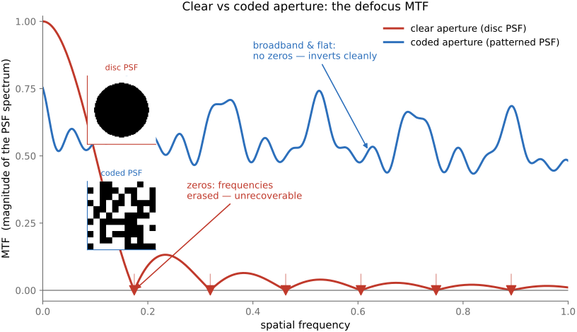
And here the disc fails twice (Figure 33.3.1). First, the Fourier transform of a uniform disc is an Airy-like function that crosses zero: it has whole rings of spatial frequency where the response is exactly nothing. A frequency the blur multiplied by zero is gone: no deconvolution can divide it back, because dividing by zero recovers nothing but amplified noise. The clear-aperture defocus does not merely scramble the high frequencies, it erases bands of them, and deconvolution at those bands is hopeless. (This is the same near-zero-MTF disease that motivated Chapter 33.1, Wavefront coding and that detonates naive inversion in Chapter 16.4, Blind deblurring.) Second, for depth, the disc is a smooth, featureless blob, so the blurred images you get at different depths look maddeningly alike. A patch blurred by a slightly bigger disc is hard to tell from the same patch blurred by a slightly smaller one, because both are just "smoothed." The clear aperture is therefore a bad operator on both counts: not invertible (zeros in the MTF) and not informative about depth (the blur signature changes too little and too gracefully with distance to be read).
33.3.2 A mask designed for a flat, zero-free spectrum⧉
The fix is to stop letting the aperture be a plain circle. Put a patterned mask in the aperture, an opaque sheet with a chosen arrangement of holes, so that the PSF is no longer a smooth disc but a broadband pattern that scales with defocus. Now the PSF is the mask's own pattern, shrunk or grown according to depth, and we get to choose that pattern. The two design goals fall straight out of the two failures above:
- A zero-free, flat MTF. Choose the hole pattern so that its Fourier transform has no zeros across the band: its spectrum stays high everywhere. Then the blur attenuates every frequency but kills none, deconvolution is a well-conditioned divide rather than a divide-by-zero, and the sharp image inverts back cleanly. The mask is optimized for conditioning over the sampled band; that is not a guarantee of stable recovery for every depth or scene.
- A depth signature you can read. A broadband, structured pattern blurred at one scale looks distinctly different from the same pattern blurred at another scale. Its spectral fingerprint shifts recognizably with the blur size. So unlike the smooth disc, the coded blur tells you, at each patch, which scale (and therefore which depth) produced it.
That is the entire trade. A clear aperture passes more light and gives a blur that is smooth, near-singular, and depth-ambiguous; a coded aperture blocks roughly half the light (the price is that an amplitude mask throws light away, unlike the lossless phase plate of Chapter 33.1, Wavefront coding) and in exchange gives a blur that is broadband, invertible, and depth-stamped.
33.3.3 One shot, two outputs: depth and an all-in-focus image⧉
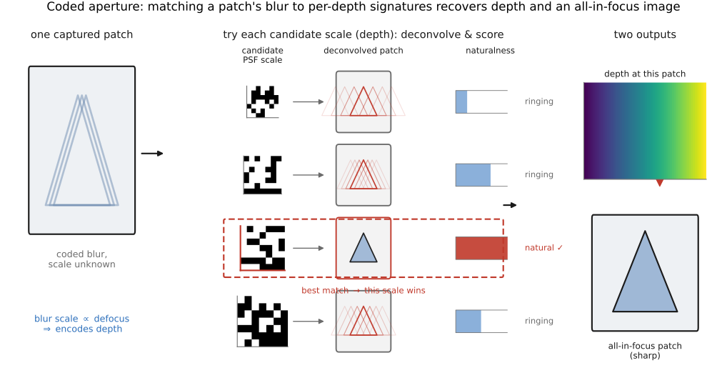
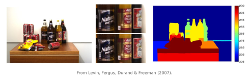
Levin, Fergus, Durand & Freeman put this together in 2007 into a method that gets both the depth map and the all-focus image from a single photograph through a coded aperture Levin et al. 2007. The decoding hinges on the depth signature, and the logic is clean (Figure 33.3.2).
The blur scale is a direct readout of depth: an object's defocus, and hence the size of the coded PSF it produces, grows with how far it is from the focus plane, so a calibrated PSF-scale estimate constrains depth. Symmetric apertures have a front/back defocus ambiguity; asymmetry can help distinguish it. Textureless or saturated patches may not reveal scale reliably. To find the scale, the decoder uses the fact that the coded blur is identifiable. It takes a small image patch and tries to deconvolve it with each candidate PSF, the mask pattern at each possible scale, and asks which deconvolution looks like a natural image and which leave tell-tale ringing and artifacts. Deconvolving with the correct scale undoes the blur and yields a clean, sharp patch with the sparse-gradient statistics of a real photo; deconvolving with the wrong scale fails to cancel the mask's pattern and leaves visible ringing, which a natural-image prior scores as implausible (this is exactly the sparse-gradient discriminator of Chapter 16.4, Blind deblurring, now used to choose depth rather than a kernel). Sweep candidate scales and score their reconstructions, then impose spatial consistency on depth labels. Ambiguous regions can require user constraints, as in the original demonstrations; the local prior alone does not identify every depth. Then deconvolve every patch with its own chosen, correct-scale PSF to get the all-in-focus image. Two outputs, one exposure, one ordinary-looking camera with a cardboard mask in the lens.
33.3.4 The design criterion: which pattern?⧉
Not every mask is a good mask, so what exactly should the pattern be? The two goals pull together into one optimization, and seeing it stated is the chapter's one piece of real design theory (kept to intuition).
The first requirement we have met: the MTF must be broadband and zero-free, so the blur preserves information and inverts well. The second is sharper than "looks different at different scales," and it is the heart of the design. We want the mask whose blurred output is maximally distinguishable across depths, so that the wrong-scale deconvolutions ring as strongly as possible and the correct scale wins unambiguously. The natural way to measure "distinguishable" is the Kullback–Leibler divergence between the distributions of images you would observe under two different depth hypotheses: a good mask makes those distributions far apart (high KL), so that no two depths produce confusable blurs, while a bad mask (the clear disc) makes them nearly identical (low KL), so depths are ambiguous. The design problem is to find the binary hole pattern that simultaneously keeps the MTF zero-free and maximizes the depth-discriminating KL divergence between hypotheses. There is no clean closed form for the winner; Levin et al. searched over candidate binary patterns under exactly these criteria and found a specific asymmetric mask that scores well on both. The principle is what matters, not the particular pattern: the mask is optimized, against an explicit criterion that couples invertibility (zero-free spectrum) to informativeness (KL between depths). This makes coded imaging an explicit design problem rather than a matter of ad hoc shape choice.
33.3.5 Coded-aperture pairs: splitting the trade across two shots⧉
A single mask has to serve two masters with one spectrum, and the masters conflict: the pattern that is best for deblurring (flat, energy spread evenly) is not quite the pattern that is best for depth discrimination (which wants structured, scale-sensitive features), so any one aperture compromises. Zhou, Lin & Nayar's answer in 2009 is to stop compromising and use two Zhou, Lin & Nayar 2009. They optimize a pair of complementary apertures and take two shots, one through each. The pair is designed so that wherever one mask's MTF has a zero, the other mask's MTF is high, so their zeros are interleaved, and together the pair covers all frequencies and deblurring from the two shots is far better than from either alone. And because the two apertures respond differently to defocus, the pair constrains relative blur. This is not a pixelwise ratio of intensities: locally, a frequency-domain relation can cancel shared latent texture where its spectrum is nonzero, while practical estimation must handle noise and boundaries. It is the same idea pushed one notch: if one designed operator forces a trade-off, design a complementary pair whose measurements jointly beat the trade-off. The cost is a second exposure.
33.3.6 Heterodyning the light field: dappled photography⧉
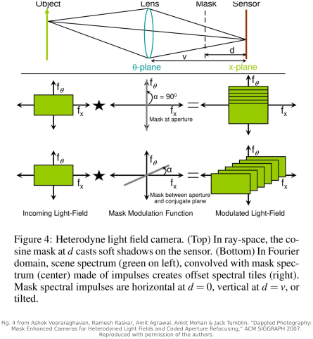
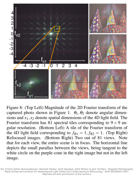
There is a cousin that moves the mask out of the aperture and places it near the sensor instead, and it reveals what coded masks are really doing. Veeraraghavan, Raskar, Agrawal, Mohan & Tumblin's "dappled photography" (2007) puts a fine patterned mask just in front of the sensor, and with it a single 2-D sensor records a coded, bandwidth-limited sampling of the 4-D light field, the bundle of rays sorted by both position and direction (Part 31, Light fields and plenoptic cameras) Veeraraghavan et al. 2007.
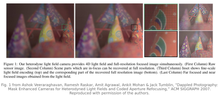
The mechanism is best named in the frequency domain, and the word for it is borrowed from radio: heterodyning. A light field has a 4-D spectrum, and the angular (directional) information lives in high-frequency bands that a plain 2-D sensor cannot reach: they would simply alias away. The sensor-side mask is a fine pattern of tiles, which in the frequency domain is essentially a sum of cosines at chosen carrier frequencies. Multiplying the light field by that mask replicates and shifts the light field's spectrum to those carriers, exactly what a radio mixer does when it heterodynes a signal up or down in frequency. The shift folds the otherwise unreachable angular bands down into the range the 2-D sensor can record. One 2-D capture carries selected spatial-angular bands within its finite sample budget, modulated into recoverable bands, which a computational demodulation unpacks. From that light field you can refocus and change viewpoint after the fact. And the same paper notes the duality with this chapter: put a comparable mask in the aperture instead of at the sensor and you are doing coded-aperture refocusing: the mask's job is to make the camera's projection of the light field invertible, whether it codes the spatial blur (aperture) or the angular bands (sensor). The clean account of why either placement works (what each does to the support and conditioning of the camera's projection in the 4-D light-field spectrum) is exactly the subject of Chapter 33.6, Theoretical analysis of imaging systems in the 4D light field Fourier domain.
33.3.7 Where it sits⧉
Coded aperture is the amplitude sibling in the part's family of pupil codes, and naming its relatives places it. Its closest sibling is Chapter 33.1, Wavefront coding, and these examples make an instructive contrast: both engineer the PSF, but toward opposite ends. Wavefront coding uses an ideally nonabsorbing phase plate to make the blur depth-invariant, an approximately fixed kernel over a designed depth range, so a single deconvolution sharpens everything and depth information is deliberately thrown away. Coded aperture uses an amplitude mask (lossy and light-blocking) to make the blur depth-dependent but identifiable, so depth information is deliberately kept and read out. One suppresses depth dependence for extended depth of field; the other exploits it for depth estimation. Other phase designs can encode depth too, so this is a comparison of designs, not a universal amplitude/phase division. They correspond to the two ways to modify a pupil: shape its phase or shape its amplitude. Both apply to the same underlying idea: make the optical encoder produce a blur that computation can decode.
That decode (how you invert a known, well-conditioned blur, and how the sparse-gradient prior tells a good deconvolution from a ringing one) is the machinery of Chapter 16.4, Blind deblurring, which this chapter has leaned on throughout. Here we needed only the promise that a broadband, zero-free, depth-stamped blur is one you can both invert and read. Design such a blur into the aperture, and a flat photograph stops throwing away its depth and starts handing it back, sharp scene and distance map together, from a single click.