11.6 Perspective distortion and its correction⧉
You photograph a cathedral. Standing at its foot, you tilt the camera up to fit the spire in the frame, and the result has a defect you did not put there and cannot quite name: the two towers, which you know to be plumb and parallel, lean toward each other as they rise, as though the building were tapering to a point somewhere above the clouds. This is keystoning, or converging verticals, and architectural photographers find it objectionable enough that an entire class of equipment, and an entire panel of software tools, exists to undo it.
The first instinct is to blame the lens. It is the wrong instinct, and correcting it is the whole point of this chapter. Keystoning is not an optical defect; it is perspective projection doing exactly its job. The same geometry that makes railroad tracks meet at the horizon makes a bundle of parallel verticals converge when you tilt the sensor off the wall. Once you see it that way, the cure writes itself. Because the leaning-tower image is a perspective image of a real, flat, rectangular façade, a single projective warp, a homography, the top rung of the degrees-of-freedom ladder from Chapter 11.1, Warping, can re-render that façade as if the camera had been aimed straight at it, sensor parallel to the wall, verticals plumb. This chapter is that one move: why the distortion is projection and not optics, how to recover the homography (by hand from four corners, or automatically from vanishing points), the optical way to dodge it at capture (the tilt-shift lens), and the price you pay for fixing it in software (you resample, and only a plane comes out exactly right).
11.6.1 Keystoning is projection, not a lens flaw⧉
Start with the symptom and pin down exactly when it appears. Aim the camera up at a tall building and its parallel verticals converge toward the top; aim it down and they splay apart toward the bottom. A wide-angle lens makes the same projective effect read as an exaggerated near/far stretch: the close end of a façade looms huge, the far end shrinks away. None of this is the glass misbehaving.
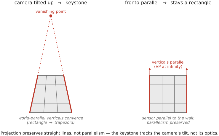
The cause is the single fact about perspective projection to keep in mind: projection preserves straight lines, but not parallelism, angles, or lengths. A straight line in the world images as a straight line. That survives. But a bundle of lines that are parallel in the world need not stay parallel in the image; instead they image as a bundle of lines converging to a single point, the vanishing point (the image of the point at infinity where the world parallels "meet"). The towers stay perfectly straight in your photograph; they simply stop being parallel. That is projection, not aberration (Figure 11.6.1).
Contrast this with the one perspective-like artifact that is an optical defect: radial lens distortion, barrel and pincushion, which bends straight lines into curves and comes from the lens. Keystoning bends nothing. If you lay a ruler along a keystoned tower the edge is dead straight; the lines have only lost their parallelism. The two corrections are different operations on different causes: radial distortion is undone by a nonlinear radial warp (a lens-distortion model), keystoning by the linear projective warp of this chapter, a contrast developed in detail in Part 22, Compound lenses, and aberration correction (Aberrations correction: radial distortion correction), where that lens defect and its cure now live.
The giveaway that fixes the cause precisely: if the image plane is parallel to the subject plane, sensor parallel to the façade, then world lines that are parallel to the sensor stay parallel in the image, and there is no convergence at all. Convergence appears exactly when you tilt the sensor off the wall. So keystoning is a function of nothing but camera orientation relative to the plane you care about, and a quantity that depends only on orientation is precisely the kind of thing a homography can undo.
11.6.2 The fix is a homography: re-render the façade fronto-parallel⧉
Your keystoned photograph is a perspective image of a genuine planar rectangle, the façade. And a basic fact of projective geometry is that a homography maps between any two images of a plane. So there exists a single $3\times3$ projective warp $H$ that takes your tilted-sensor image of the façade to the image you would have captured with the sensor parallel to the wall: sending the converging lines back to parallel, the trapezoid back to a rectangle. This is precisely the projective rung of the degrees-of-freedom ladder from Chapter 11.1, Warping, used here with the target being a fronto-parallel rectangle of your choosing (Figure 11.6.2).
A plane supplies a depth relation that converts perspective projection between cameras into one projective map. Pure rotation about the camera center is a separate homography case that does not require the scene to be planar. Neither statement makes general camera translation depth-independent.
There are two ways to recover $H$.
Method 1: four corner correspondences. Pick four points in the photograph that you know bound a real rectangle (the four corners of a window, or of the façade outline) and specify where each should land: the four corners of a true rectangle, verticals vertical, horizontals horizontal. A homography has 8 degrees of freedom (DOF) (a $3\times3$ matrix up to overall scale), and each point correspondence contributes two linear equations, so four correspondences exactly determine $H$; more than four overdetermine it and you solve by least squares / singular value decomposition (SVD). This is the manual perspective crop: drag four handles to the corners, declare the output a rectangle, done (Figure 11.6.2).
Vanishing points from parallel line families identify the plane’s vanishing line and can support affine rectification. Parallelizing two families does not by itself recover their true angle or the façade’s aspect ratio. Metric rectification needs additional information, such as orthogonality constraints, known dimensions or calibration Liebowitz & Zisserman 1998.
Either way, once $H$ is known you apply it by the primitive from Chapter 11.1, Warping: inverse-warp and resample. Loop over the output pixels, push each one back through $H^{-1}$ to find where it came from in the input, and resample the input there,
with the same forward-versus-inverse reasoning (loop over output, never over input, so every output pixel is filled exactly once) and the same reconstruction-filter care as every other warp in the part. Nothing about rectification is special in the applying; the only work is the solving of $H$.
In practice this is Lightroom's Transform / "Upright" panel (with auto and guided modes, where guided mode lets you draw the lines that should be vertical or horizontal), Photoshop's perspective crop, and the dedicated tools in architecture software. The user experience is "drag the building straight"; the engine underneath is the four-point or vanishing-point homography.
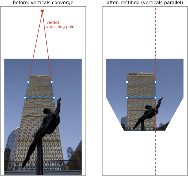
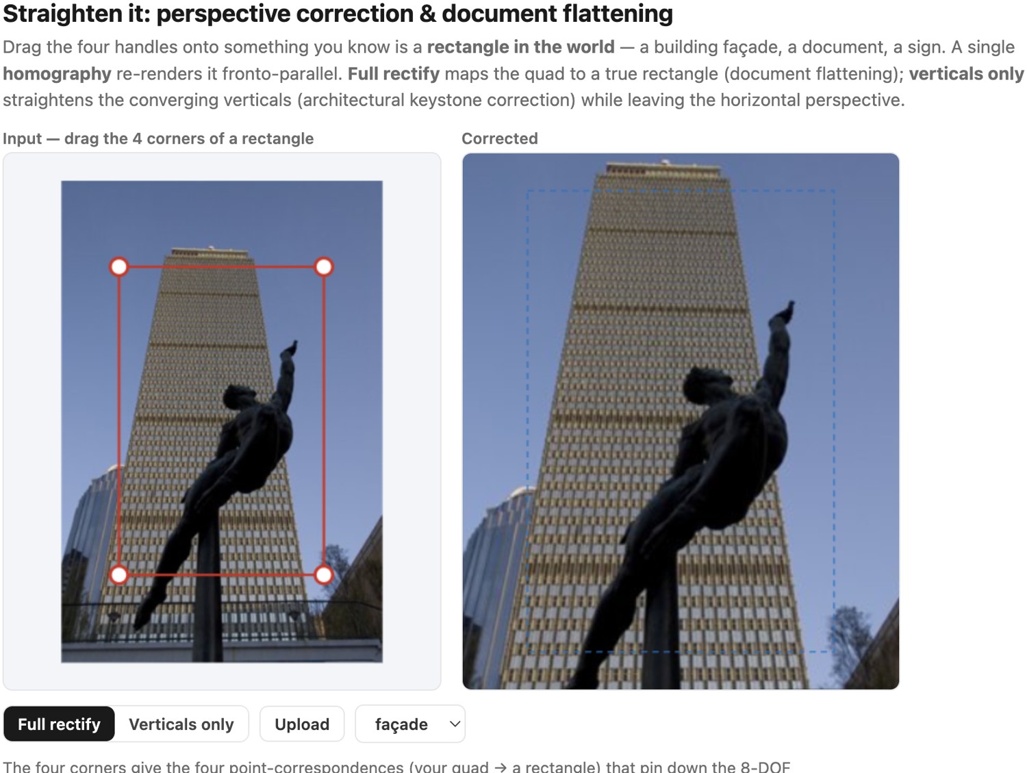
For the vanishing-point route, detect several lines believed to be parallel in the scene and estimate their common vanishing point. Sending the vertical family's vanishing point to infinity makes its lines parallel in the output; the output orientation then makes them vertical. A second independent family constrains the plane's vanishing line. This explains what automatic straightening is estimating, and why an incorrect line family or an unknown aspect ratio can still produce the wrong rectification.
11.6.3 The optical alternative at capture: tilt-shift / Scheimpflug⧉
The homography fixes perspective in post. There is an older way to fix it at capture, in the lens, so that the verticals never converge in the first place: the view camera and its modern descendant the tilt-shift lens.
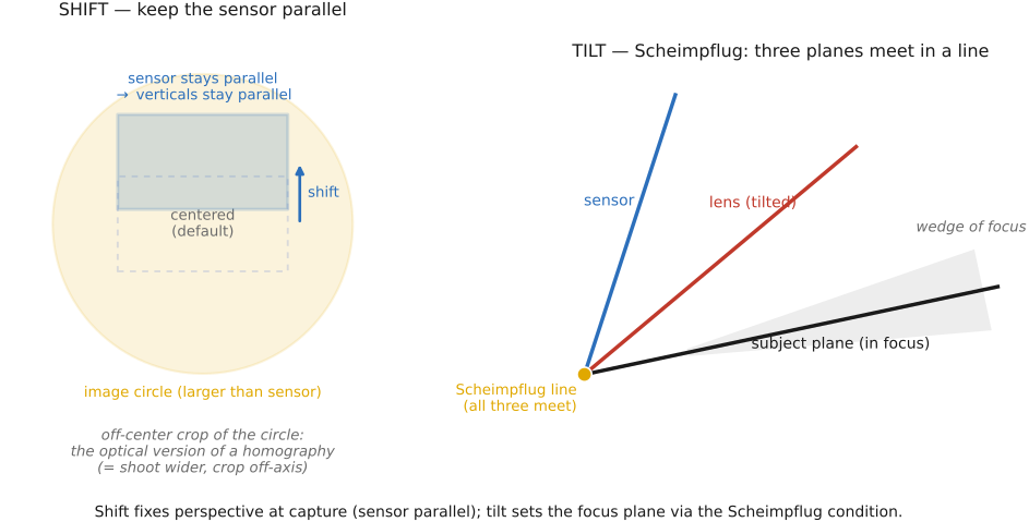
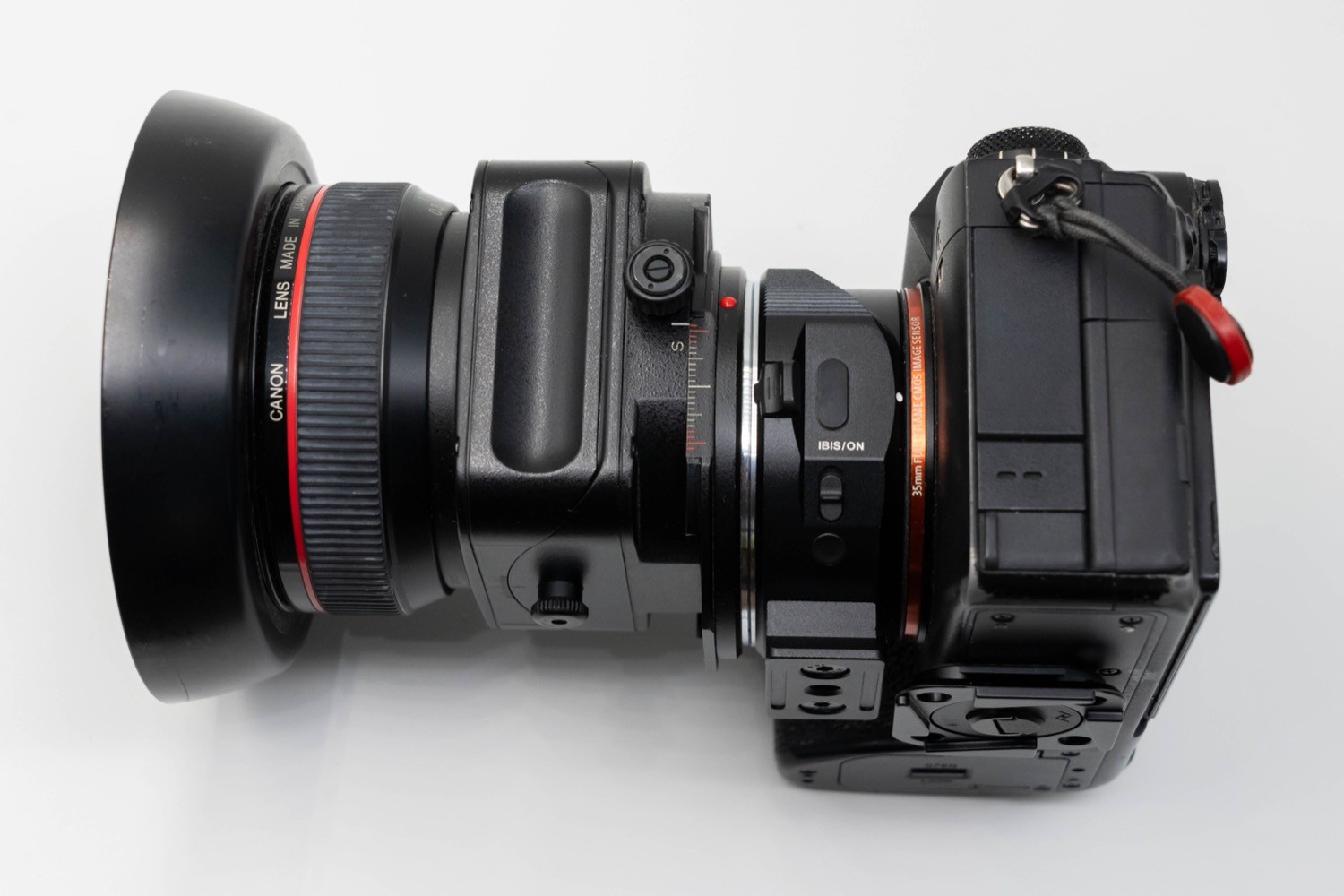
The trick is geometric. A normal lens projects an image circle just big enough to cover the sensor, centered on the sensor. A view-camera (or tilt-shift) lens projects an image circle larger than the sensor, and lets you shift the lens (or the back) sideways or up to select an off-center part of that larger circle, all while keeping the sensor parallel to the façade. Because the sensor stays parallel to the subject plane, the world verticals stay parallel in the image: no convergence, no post-warp, no resampling penalty (Figure 11.6.4). You compose the tall building by shifting the lens up rather than by tilting the camera up.
A useful way to see the shift: it is geometrically the same as taking a wider, centered shot and cropping to the off-axis region you wanted, which is exactly why a software "perspective crop" can approximate a shift lens (at the cost of resolution, since you are throwing away the rest of the frame). The shifted-sensor image and the would-be-tilted image of the same façade differ by, unsurprisingly, a homography, which is the precise sense in which the optical fix and the software fix are two routes to the same place.
The view camera's other movement, tilt, does something different: it controls the plane of focus rather than perspective, via the Scheimpflug condition (the lens plane, sensor plane, and subject plane all meet along a single line). Tilt is how you get a steeply receding plane (a tabletop, a landscape) entirely in focus at a wide aperture; reversed, it is the trick behind the "miniature/tilt-shift" toy-town look. We only note tilt-shift here as the at-capture counterpart of the rectifying homography; the optical derivation belongs to Part 22, Compound lenses, and aberration correction (Scheimpflug, image circle, the view-camera movements), cross-referenced and not repeated.
The trade-off is the familiar capture-versus-post one. The optical correction preserves resolution and avoids resampling artifacts entirely, but it demands special, expensive, manual gear and must be decided at capture. You cannot recover uncaptured detail or change the original focus plane merely by rectifying geometry. The software homography is free and deferrable (decide later, in front of the computer), but it resamples, which is the catch of the next section.
11.6.4 Cropping wide-angle photographs: recenter with a homography, don't just crop⧉
There is a workflow many photographers (this author included) have quietly adopted: shoot wide and crop later. Modern autofocus and high-resolution sensors make it painless: extend your arm over a group, aim roughly, and trust the wide-angle lens to catch everyone, then crop to the good part afterward. It is a useful way to shoot when there is no time to compose.
But it hides a subtle problem. If the interesting part sits off to one side of the wide frame and you crop it, that crop still carries wide-angle perspective distortion, with widened faces and splayed verticals, even though it now looks like a zoomed-in telephoto shot. The zoom is real (you kept fewer pixels), but the distortion is gratuitous: it is there only because the cropped region was off the optical axis, where rectilinear projection stretches hardest. The cropped region carries the wide lens's distortion, which it would not have had if you had simply aimed the camera at it.
To simulate rotating the viewing direction about the same center, use $H=K_{\rm new}RK^{-1}$ after accounting for lens distortion. Define $R$ as mapping old camera rays into the new camera frame. This applies across scene depths, but only to rays present in the input. A crop instead keeps the old image-plane orientation. Reprojection changes off-axis rendering; it cannot provide the detail of a longer-lens capture or the perspective of a camera moved farther away.
The move is everywhere a fixed wide lens must impersonate a moving telephoto one: video-surveillance virtual pan/tilt/zoom (one wide camera serving many "virtual" zoomed feeds), and action cameras, whose ultrawide footage is routinely reframed in software after the fact. Use the demo below to compare the two results. Aim at an off-center part of a real wide-angle shot, dial in a zoom, and compare the homography view against a plain crop of the same region: the plain crop keeps the wide-angle skew, the homography removes it (Figure 11.6.6). This local-projection view of wide-angle correction is the seed of the content-preserving projections in the next section Carroll, Agrawala & Agarwala 2009.
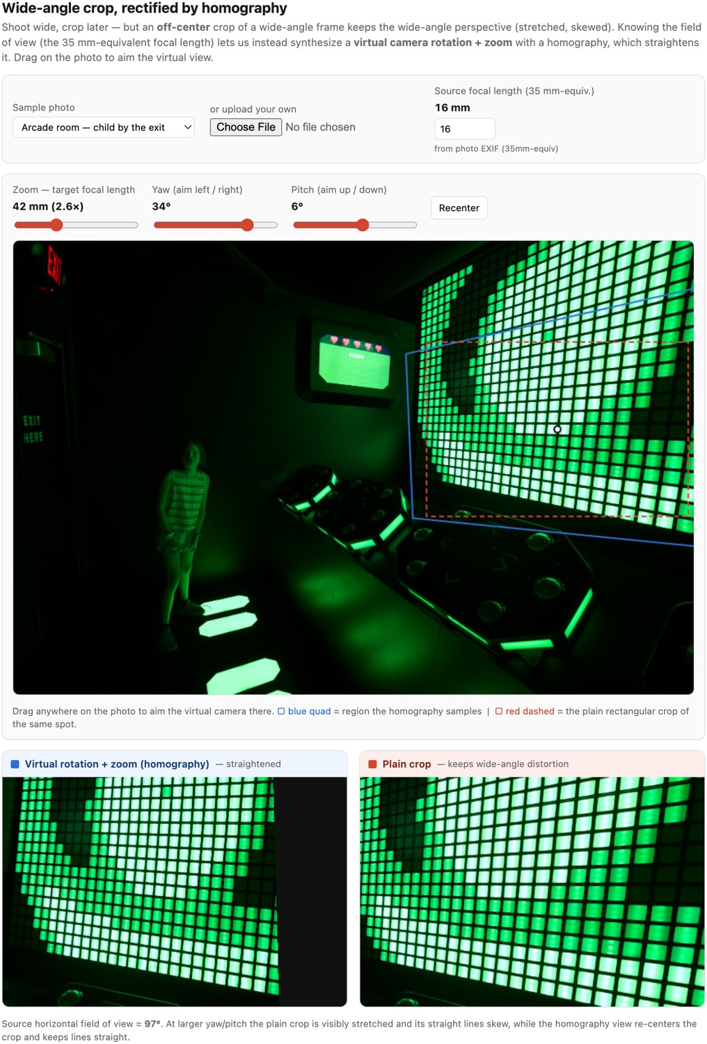
Cropping selects pixels from the existing projection; it does not change the projection center or viewing direction. A virtual camera rotation changes the coordinate system in which the captured rays are projected. With known intrinsics, reproject those rays into a new image centered on the region of interest, then choose the new focal length and crop. This can reduce the off-axis stretching left by a simple crop. It cannot supply rays outside the capture or recover detail lost to resampling, and straightening one set of lines does not guarantee every three-dimensional surface has become fronto-parallel.
11.6.5 A different perspective distortion: wide-angle portraits, and a content-aware fix⧉
Keystoning is the perspective distortion that comes from tilting the camera. There is a second kind that comes from a wide field of view, and it needs a different cure. As Chapter 2.2, Pinhole image formation and linear perspective, showed, rectilinear projection onto a flat sensor stretches solid shapes toward the frame edges: a sphere images as a radial ellipse, and faces near the edge of a wide-angle or group photo look widened and skewed. Nothing is bent (straight lines stay straight), so this is not lens distortion and a homography cannot undo it: a single projective warp re-renders one plane, but here the offenders are 3-D faces scattered across the field, each wanting a different local correction.
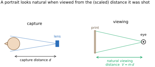
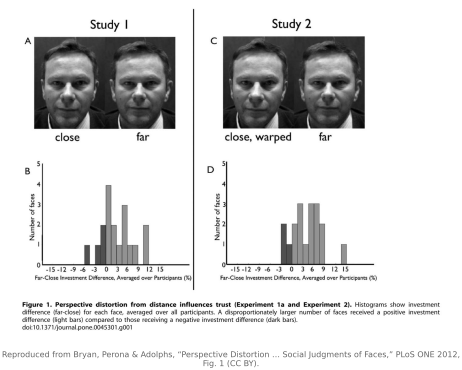
There is a deeper reason to bother, and it is perceptual, not merely geometric. A face shot up close with a wide lens, with the nose looming and the ears receding, does not just look stretched; it looks like a different person. Pietro Perona's A new perspective on portraiture (Perona 2007, J. Vision 7(9):992) made the point sharply: the perceived shape of a face, and even the personality we read off it, depend on the camera-to-subject distance, because near and far parts of a 3-D face foreshorten differently at close range and barely at all from afar. Follow-up work confirms that the traits viewers attribute to a face (trustworthiness, competence, attractiveness) shift measurably with shooting distance (Bryan et al. 2012). This is the same focal-length-and-distance fact behind the classic advice to shoot portraits from a few meters back with a moderate telephoto rather than up close with a wide lens; cross-reference the portrait-lens discussion in Part 2, Fundamentals (Photography 101). A perceptual correction changes the chosen rendering; it does not recover a unique undistorted identity from an image.
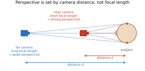
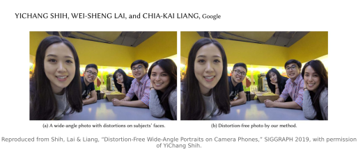
The fix is to change the projection locally. It must be local for geometric reasons: no single global projection can keep both straight lines straight and object shapes undistorted across a wide field of view. Zorin and Barr made this precise in Correction of Geometric Perceptual Distortions in Pictures (Zorin & Barr 1995), trading off perspective against a direct/spherical projection to minimize perceived distortion; Carroll, Agrawala and Agarwala's Optimizing Content-Preserving Projections for Wide-Angle Images (Carroll, Agrawala & Agarwala 2009) turned it into an optimization that keeps user-marked lines straight while relaxing the projection elsewhere. A stereographic projection maps the sphere of viewing directions to the plane conformally: it preserves local shapes (a face stays face-shaped) at the cost of gently bending some straight lines. Applying it everywhere would bow the architecture; keeping perspective everywhere stretches the faces. Shih, Lai & Liang's distortion-free wide-angle portraits (Shih et al. 2019) get both right with a content-aware mesh warp: the mesh follows the stereographic map inside detected face regions (so faces look natural) and the original perspective map elsewhere (so background lines stay straight), with a smooth transition between, recovered by minimizing a per-vertex energy. It corrects the edge faces while leaving the room straight. This is the warp engine of Chapter 11.1, Warping, steered by where the faces are (Figure 11.6.10).

11.6.6 Beyond faces: correcting arbitrary objects (MaDCoW)⧉
Shih et al.'s warp is steered by faces, because faces are what a detector can reliably find and what viewers most object to seeing stretched. But the same marginal distortion afflicts anything solid near the edge of a wide frame: a coffee cup, a car, a whole body, an ornament on a building. MaDCoW (Zhang, Huang, Echevarria, DiVerdi & Hertzmann, Zhang et al. 2025) drops the face-only restriction. The user marks the straight lines that must stay straight and the regions of interest that must keep their shape; MaDCoW then solves a local linear-perspective projection for each region and jointly fits a single distortion-minimizing projection for the whole frame that honors those local perspectives while keeping the marked lines straight. Each object is re-rendered as if the camera had been aimed at it, and the frame is stitched from those local views, so objects that Carroll's global-ish projection or Shih's face-only warp still leave visibly warped come out natural.
The move is the one this whole family of corrections keeps rediscovering: no single global projection can serve a wide field of view, so you give each region its own local perspective and blend. It is also the engineering echo of how the perception works. The visual system reads a picture's shapes per fixation, around wherever the eye lands (the perceptual story in Chapter 5.6, Preparing photographs for viewing, Robustness of perspective to the viewer's viewpoint), so a correction that gives every object its own locally-consistent perspective is aligned with how a viewer looks at the scene to begin with. That is no coincidence: Hertzmann is behind both the perceptual theory and this algorithm.
11.6.7 A montage has no single viewpoint: a family in a box⧉
Keystoning came from one viewpoint tilted; wide-angle stretch from one viewpoint too close. There is a third, sharper way to break perspective: use many viewpoints at once and tile them into a single frame. A photographic montage does exactly that, and a New Year card one of us made, "family in a box" (Durand 2023), makes the geometry impossible to miss. Every family member, each cat, and every stuffy was photographed head-on inside the same cardboard box, and the shots were tiled into a $4\times13$ grid of boxes. The card is charming and geometrically inconsistent: the perspective is wrong, because each box was shot straight on and therefore carries its own virtual viewpoint. There is no single camera anywhere that would produce that picture (the card itself is Figure 11.6.12, below).
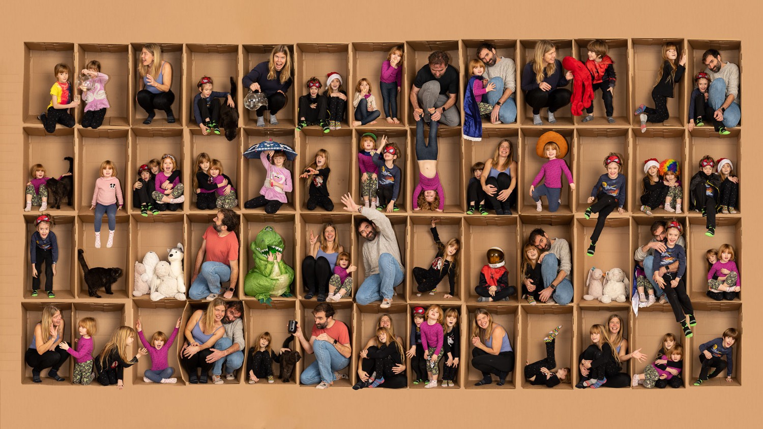
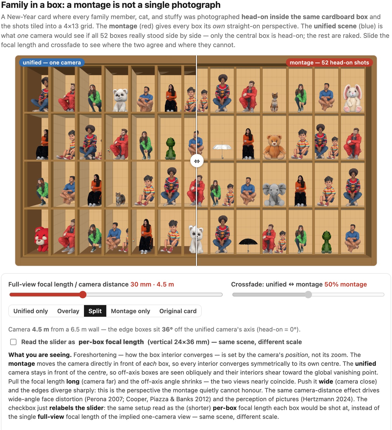
Why this is the same story told backwards: a correct perspective image has one center of projection. Aim a single camera at a real wall of $4\times13$ boxes standing side by side, and only the central box is seen fronto-parallel; every other box is off-axis, so the camera looks into it obliquely and its interior walls shear toward the scene's global vanishing point: the boxes at the far edges are raked hard, exactly the keystoning of the first section but now sideways and per-tile. The montage refuses all of that: it re-centers the camera on each box, so every interior converges symmetrically to its own middle, as if you had $52$ cameras instead of one. The give-away is the same quantity that governed keystoning and portrait distortion (the camera's position relative to each subject), and the montage quietly assigns a different position to every tile.
The interactive real-3D demo in Figure 11.6.13 puts the two side by side, literally on top of each other. It builds the $52$ boxes as actual geometry, fills them with the cast, and renders the grid two ways: the montage (each box shot head-on, its own perspective) and the unified scene (one camera in front of the center, the rest oblique). A single control sets the focal length / camera distance of that one camera. Pull it long (camera far, telephoto) and the off-axis angle to the edge boxes shrinks toward zero: the rays become nearly parallel (the orthographic limit), every box is seen almost head-on, and the unified view converges onto the montage. Push it wide (camera close) and the edges diverge sharply: the unified scene rakes its corner boxes while the montage holds every one of them flat. They agree only in the long-lens limit and disagree exactly where real single-viewpoint perspective would bite.
The card still looks fine, which connects this chapter to how perspective is actually perceived. Human viewers are strikingly tolerant of the "wrong" station point: Cooper, Piazza & Banks (Cooper et al. 2012, The perceptual basis of common photographic practice) showed that we do not rigidly reconstruct the camera's true position from a picture: we have a strong preferred viewing geometry (the reason a $\sim$50 mm "normal" lens, viewed at a comfortable distance, looks undistorted) and we forgive wide departures from it rather than seeing the scene warp. Hertzmann (Hertzmann 2024, Toward a theory of perspective perception in pictures) pushes this further into a theory in which eye fixation and foveal vision carry the perception of 3-D shape and space in a picture, which is why spheres and faces at the margins of a wide frame look distorted while the same content near where you look does not, and this also explains why a montage of locally head-on tiles reads as natural even though it composes into no global perspective at all. The montage exploits exactly this tolerance: every tile is locally perfect, and the visual system never demands that they share a viewpoint. It is the perceptual flip side of the portrait result above. The same camera-distance geometry that makes a close wide-angle face look like a different person (Perona 2007; Bryan et al. 2012) is the geometry a montage scatters across the frame and gets away with.
11.6.8 Recomposing perspective after capture: computational zoom⧉
The montage assigned a viewpoint per tile by hand. Computational zoom (Badki, Gallo, Kautz & Sen, Badki et al. 2017) is the continuous, automatic version. Instead of one exposure you capture a short stack of photos of a static scene as you walk toward (or away from) the subject; the system reconstructs the scene's depth from that stack and then lets you composite a new image with a perspective you choose after the fact. You can slide the relative size of foreground and background, the dolly-zoom lever of Chapter 2.2, Pinhole image formation and linear perspective (focal length versus distance), now a post-capture control, and, more radically, hand different parts of the frame different perspectives in a single seamless picture, a multi-perspective composition that corresponds to no physical camera at all (much like the montage, but continuous and photographic rather than tiled by hand). It turns the choice of station point, normally frozen at the instant of capture, into a parameter you can edit afterward.
11.6.9 The catch: resampling cost, and "only a plane rectifies exactly"⧉
The software homography is free, but it is not free of consequences. Two caveats bound what it can actually do.
Rectification resamples, and resamples non-uniformly. To make the far (top) of a tilted façade as wide as the near (bottom) edge, the homography must enlarge the top of the image and compress the bottom. The output therefore has non-uniform resolution: the formerly-far corners are stretched and come out soft (interpolation invents no new detail: recovering plausible high frequencies would be super-resolution, a different, prior-driven problem, cross-ref Chapter 14.1, What can super-resolution actually do?), while other regions are squeezed. And wherever the warp shrinks the image, you are throwing samples away, so you must prefilter before downsampling or the fine detail folds into moiré. This is big lesson L16 again. A faithful rectifier applies the prefilter per region, with the kernel footprint set by the local Jacobian of $H$ (how much area each output pixel covers in the input), so the shrinking regions are area-averaged and the enlarging regions are merely interpolated.
Prefilter the shrinking corners. Rectification does not resample uniformly. To square up a tilted façade the homography enlarges the far/top corners (upsampling: just interpolate, no prefilter) and compresses other regions (downsampling: you must prefilter, or alias). So a faithful rectifier applies the prefilter-before-downsample discipline region by region, with the reconstruction kernel widened according to the local Jacobian of $H$ (the local shrink factor) exactly as a global minify widens its kernel by the downscale factor. (L16, first placed in Chapter 11.1, Warping / BASIC: Resampling; this is one of its geometric recurrences.)
You lose frame and pixels. The rectified rectangle generally does not fill the original frame: its corners read outside the input (handled by the boundary policy from Chapter 11.1, Warping: pad, clamp, or mark undefined), and you usually crop to the valid interior, sacrificing field of view and resolution. "Upright" with auto-crop is just managing exactly this: finding the largest upright rectangle that stays inside the warped image.
A homography relates views of one plane under general camera motion, or views of arbitrary depths under pure rotation about one projection center. Translation creates depth-dependent parallax. Depth-based warping can handle visible correspondences, but newly exposed surfaces still need additional imagery or inference. These are different limits from planar façade rectification.
11.6.10 Where this sits: one map, then transport⧉
In Chapter 8.13, A raw developer in the browser, Vertical and Horizontal are the true rotate-and-reproject of this chapter (never a keystone), guided Upright solves marked lines jointly, and the crop tool's Re-aim recenters an off-axis crop with the homography of the wide-angle section: one resample for all of it.
The geometric estimation changes across applications, but applying the result does not. Here the target is a chosen rectified view; in Chapter 20.1, Manual panorama stitching from multiple views it is another photograph. Both require a map with the right geometric assumptions, followed by backward lookup and resampling. A dense optical-flow field supplies a richer map without removing the same questions about visibility, valid support and sampling.
11.6.11 Robustness of perspective to the viewer's viewpoint⧉
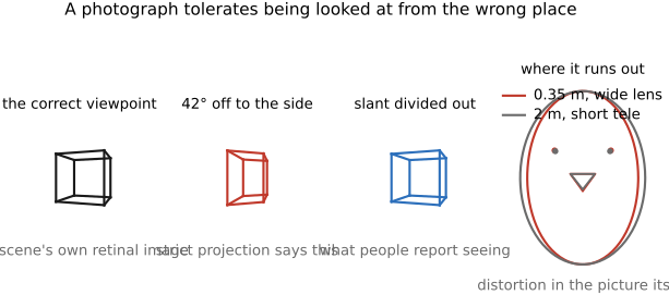
A perspective picture reproduces the taking camera's ray directions from a particular scaled viewing position. From another position the picture surface projects differently onto the retina. Yet we can often interpret a photograph from an oblique seat without perceiving the full distortion predicted by that geometry.
Pirenne Pirenne 1970 discussed compensation based on information about the picture surface; Kubovy Kubovy 1986 relates viewing geometry to pictorial practice. Vishwanath, Girshick and Banks Vishwanath, Girshick & Banks 2005 tested perceived shape while varying viewing conditions and information about surface orientation. Their findings support an influence of estimated surface orientation. They do not establish that the viewer explicitly recovers the original camera center and inverts the entire projective transform.
Other experiments and analyses report incomplete compensation and systematic distortions. Yang and Kubovy Yang & Kubovy 1999 found that observers neither fully compensate for nor fully experience the transformations geometry predicts, and demonstrated a cuboid illusion in which a depicted box's perceived shape depends systematically on the picture's orientation and position even when surface cues are abundant. Todorović's direct tests reach a similar verdict Todorović 2008. Perkins gave an early empirical treatment of compensation for oblique viewing Perkins 1973. Koenderink and colleagues Koenderink et al. 2004 emphasize pictorial space as a perceptual interpretation. These accounts differ in their tasks and explanatory aims; viewing tolerance is not one universal correction factor.
Hertzmann's fixation-centered perspective hypothesis Hertzmann 2024 proposes that shape is interpreted locally around fixation. It offers an account of why peripheral wide-angle shapes can appear distorted and why some locally adjusted depictions work better. Martin, Gutierrez, Masia, DiVerdi and Hertzmann tested it and report that viewers' shape judgments follow the perspective around each fixation Martin et al. 2025 (per-fixation perspective). Treat it as a supported proposal with open empirical questions, not a settled replacement for all earlier results.
The engineering connection is limited but useful. A content-aware projection can preserve selected shapes that a single global perspective stretches. Evaluate that correction at relevant viewing positions and against its costs elsewhere in the image. A geometric warp alone cannot establish how all viewers will perceive the result.
Recap: big lessons of this chapter
Prefilter the shrinking corners. Rectification does not resample uniformly. To square up a tilted façade the homography enlarges the far/top corners (upsampling: just interpolate, no prefilter) and compresses other regions (downsampling: you must prefilter, or alias). So a faithful rectifier applies the prefilter-before-downsample discipline region by region, with the reconstruction kernel widened according to the local Jacobian of $H$ (the local shrink factor) exactly as a global minify widens its kernel by the downscale factor. (L16, first placed in Chapter 11.1, Warping / BASIC: Resampling; this is one of its geometric recurrences.)