36.6 Structured light scanning⧉
Passive stereo fails exactly where the scene gives it nothing to match: a blank white wall, a smooth ceramic mug, a featureless cheek. The fix is to stop relying on the scene's texture and supply your own. Structured light projects a known pattern onto the scene and recovers depth from how a camera, offset from the projector, sees that pattern land on the surface. It is the active workhorse behind 3-D scanners, the original Kinect, and the dot projectors in phone face-unlock.
36.6.1 Projector as inverse camera: triangulation with trivial correspondence⧉
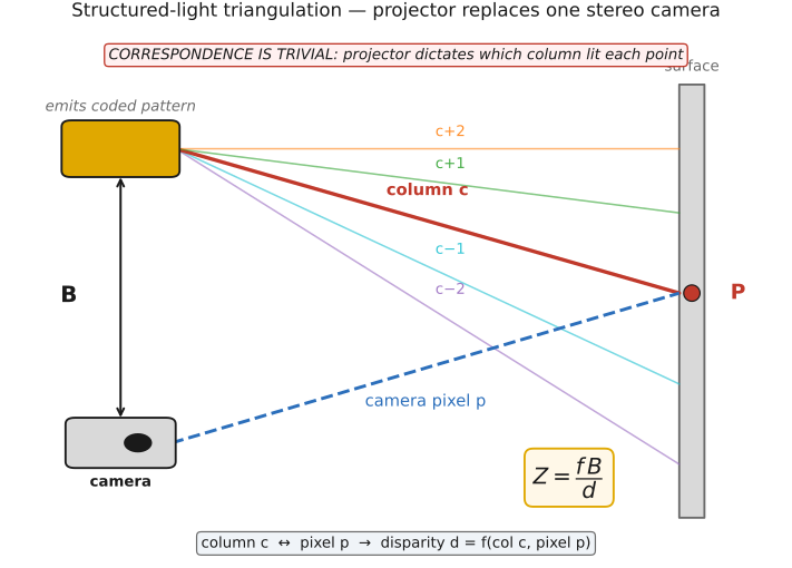
The geometry is the geometry of stereo, with one camera swapped for a projector. A projector is, optically, a camera run in reverse: where a camera maps incoming rays to pixels, a projector maps "pixels" (pattern elements) to outgoing rays. So a projector and a camera, separated by a baseline $B$, form a triangulation pair exactly like two cameras, and depth comes from calibrated ray/plane intersection, or $Z=fB/d$ in a rectified coordinate system, where the disparity $d$ is now the offset between the projector column that lit a surface point and the camera pixel that sees it (Figure 36.6.1).
What changes is correspondence. In passive stereo, finding which camera pixel matches which is the hard, error-prone search that fails on textureless surfaces. In structured light, you designed the pattern, so each surface point carries a code that names the projector column (or row) that illuminated it. The camera reads the code off each pixel and the match can be decoded even on an otherwise blank wall. Code repetition, projector blur, noise, shadows, and indirect light still create ambiguity. Correspondence, the bottleneck of passive stereo, is made easier by a known code, but must still be inferred from its measured appearance. The optimized degree of freedom is the illumination pattern itself, designed so that the camera can uniquely decode each pixel's projector coordinate.
36.6.2 The coding ladder, and the frames-versus-motion trade⧉
The design space is the set of coding schemes, how to pattern the light so the camera can decode each pixel's projector coordinate (Figure 36.6.2). They form a ladder:
- Swept single stripe. Sweep one bright line across the scene over time; the frame in which a pixel lights up names its projector column. Conceptually simplest, accurate, but needs as many frames as there are columns, so it is very slow, static scenes only.
- Binary / Gray code. Project a sequence of black-and-white bar patterns of doubling frequency; each frame contributes one bit of the projector-column index, so $\lceil\log_2 N\rceil$ ideal bit-pattern frames label $N$ columns. Complementary patterns and reference frames add robustness and increase the capture count. Gray code orders the bit patterns so adjacent columns differ by a single bit, making decoding robust to boundary errors. Far fewer frames than a swept stripe, still multi-shot.
- Phase-shifting sinusoids. Project a few (typically three or more) sinusoidal intensity patterns shifted in phase; per-pixel the recovered phase gives a sub-pixel estimate of projector position from just a handful of frames. High accuracy and few frames, but the phase wraps (it is only known modulo $2\pi$), so it needs unwrapping, often by combining with a coarse Gray code.
- Single-shot spatially-coded patterns. Encode the projector coordinate spatially within one frame: a pseudo-random speckle pattern or a De Bruijn-coded grid whose local neighborhood is unique. One frame avoids inter-pattern motion, though motion during the exposure can still blur the code; the cost is lower spatial density and more decoding fragility. The original Kinect v1 Smíšek et al. 2013 used exactly this, an infrared speckle pattern decoded in a single shot.
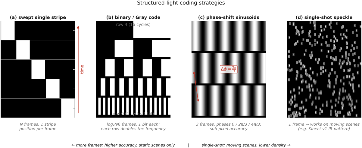
The recurring design decision is precisely this frames-versus-motion trade: many frames (swept stripe, Gray code, dense phase-shift) give the most accurate, densest depth but freeze the scene; a single shot tolerates motion but gives less. The coding-strategy literature Salvi et al. 2010 (structured-light patterns) Geng 2011 (structured light) surveys the full zoo; for the highest-accuracy ground truth depth (the kind used to benchmark passive stereo), structured light combined with many frames is the gold standard Scharstein & Szeliski 2003 (structured-light stereo) (it is how the Middlebury depth maps were made).
36.6.3 Calibration and failure modes⧉
Like any triangulation system, the projector–camera pair must be calibrated: the camera's intrinsics, the projector's intrinsics (treating it as an inverse camera), and the relative pose between them. Once calibrated, decoding a pixel's code yields its projector column, hence disparity, hence metric depth.
The failure modes mirror the assumptions. Specular surfaces reflect the pattern away from the camera or create bright virtual images that confuse decoding. Translucent and subsurface-scattering materials (skin, marble, wax) blur the projected code as light enters and re-emerges elsewhere, smearing the correspondence. Interreflections in concavities let a lit region bounce light onto an unlit region, corrupting the code there, which is why direct/global separation (the high-frequency-pattern trick of the direct/indirect chapter) is used as a pre-process for structured-light scanning on glossy or translucent objects: reducing global contamination can improve decoding when the separation assumptions hold. And bright ambient light (sunlight outdoors) can wash out the projected pattern entirely, which is why structured light is mostly an indoor technique and why outdoor systems need sufficient source power, spectral filtering, and suitable coding. Time-of-flight also faces sunlight interference; Kinect v2 was not a general solution for outdoor scanning. The pairing to remember: structured light patterns the illumination to manufacture correspondence; that is the same "the spatial pattern of light is a design variable" thesis that runs through Part 35, Computational illumination, here pointed at recovering shape.