35.4 Separation of direct and global illumination⧉
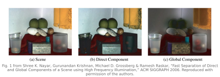
Every pixel in a photograph is a sum of two very different kinds of light, and they are usually hopelessly entangled. There is the direct component: light from the source that struck the surface point you are looking at, bounced once, and came to the camera. And there is the global (or indirect) component: light that reached that point only after bouncing off other surfaces, such as diffuse interreflections in a corner, subsurface scattering through skin or marble or a grape, translucency, volumetric scattering through fog or murky water. The direct part carries the surface's own shape and shading and its sharp specular highlights; the global part is the soft, color-bleeding glow that makes a real room look real and skin look alive. For decades, separating them required either elaborate physical models or measuring the full light-transport of the scene. Nayar, Krishnan, Grossberg and Raskar (2006) showed that, under a spatial-spread assumption for global transport, complementary high-frequency patterns can separate the components. Practical capture commonly uses several shifted patterns. It is one of the cleanest results in computational illumination.
35.4.1 The frequency insight⧉
Replace the scene's flat illumination with a projector displaying a high-frequency checkerboard, a fine pattern of lit and unlit cells, where "high frequency" just means the cells are small relative to the scale at which light spreads around the scene. Now consider a single surface point $p$ and ask what reaches the camera from it.
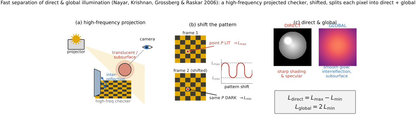
The direct radiance at $p$ depends on one thing only: whether the projector cell illuminating $p$ is currently on or off. If that cell is on, $p$ is directly lit and returns its full direct component; if off, $p$ receives no direct light and returns none. Projector blur and finite contrast weaken this on/off distinction. Narrow specular interreflections or shallow scattering may retain the pattern rather than average it, violating the global-term assumption. Direct light is local: it responds to the illumination at that point.
The global radiance at $p$ is different in kind. It is the sum of light arriving at $p$ from all the other points in the scene that themselves are (or are not) lit, integrated over a wide region, including interreflections off nearby walls, the light that entered the surface elsewhere and scattered to $p$ underneath. Because the checkerboard is high-frequency, any sizeable patch of the scene contains roughly equal areas of lit and unlit cells. So the wide average that produces the global component at $p$ is nearly the same whether or not $p$'s own cell happens to be on. The global term samples so many cells that it always sees about half of them lit. Global light is non-local, and to a high-frequency pattern it is approximately constant (Figure 35.4.2).
That asymmetry is what the method exploits. Shift the checkerboard pattern through its complementary positions and observe each surface point both lit (direct on, call its value $L_{\max}$) and unlit (direct off, $L_{\min}$). Under the lit pattern the camera sees direct-plus-global; under the unlit pattern it sees only global, and the global part is the same in both. Per pixel, then,
where $L_d$ is the direct component and $L_g$ the global. (The factor of two appears because when half the pattern is lit, a point's "off" image still received global light from the lit half of the scene, about half the global it would receive under full illumination, so $L_{\min}$ is roughly half the true global, and $2L_{\min}$ recovers it.) With linear, unsaturated, registered measurements and ambient light removed, two ideal images, or in practice a set of shifted patterns to handle that each point be seen both lit and unlit, and a subtraction estimate each pixel's decomposition into the sharp, surface-bound direct image and the soft, glowing global image (Figure 35.4.2). Run it on a face and the direct image shows skin texture and pores while the global image shows the warm subsurface glow; run it on a bowl of fruit and the global image lights up with the translucency of the grapes and the color bleeding between them; run it in a corner and the global image reveals the interreflected wash that the direct image lacks.
35.4.2 Nayar's program: programmable, structured illumination⧉
Direct/global separation is one move in a larger research program that runs through Shree Nayar's lab: treat both the camera and the illumination as programmable, and design the pattern of light (and of the sensor) to make a hard measurement easy. The common thread is structured illumination: deliberately patterning the light in space, time, or intensity so that the captured images encode something a flat-lit photo cannot.
The same lab's assorted pixels (Nayar and Narasimhan 2002) make the dual move on the sensor side: tile the focal plane with pixels of different exposures, spectral filters, or polarizations, forming a generalized mosaic beyond the plain Bayer pattern, and demosaic to trade resolution for extra dynamic range, spectral bands, or polarization channels. Direct/global separation patterns the light; assorted pixels pattern the sensor; together they sketch Nayar's generalized imaging thesis, that a camera is a programmable device whose illumination, optics, and detector are all design variables to be co-optimized for the task, not fixed givens. This is the same philosophy that animates coded aperture, coded exposure, and the rest of the computational-camera material, but here the light is the coded element, which is why it lives in COMPUTATIONAL ILLUMINATION.
Structured illumination has a second great use the separation method shares hardware with: structured-light 3-D scanning. Project a known pattern (stripes, a checker, a Gray code, a phase-shifted sinusoid) and read the scene's geometry from how the pattern deforms across it. This is the active-illumination workhorse behind depth sensors and 3-D scanners. Direct/global separation can improve structured-light scanning on translucent or interreflecting objects: global transport can corrupt the pattern the scanner is trying to decode, so removing it (by exactly the high-frequency trick above) cleans up depth estimates on skin, marble, and glossy concavities. Pattern the light one way to measure shape and another way to separate transport. It is the same instrument with two different codings.
35.4.3 Toward coherent separation⧉
Nayar's separation isolates the direct component by spatial pattern: a point is direct-lit iff its own high-frequency cell is on. There is a second, complementary way to isolate the same direct or single-scattered light, using focus and coherence, and it is the subject of Chapter 35.8, Coherent imaging. Confocality does not require coherent illumination. A confocal system co-focuses the source and the detector on a single point through conjugate pinholes, so that single-scattered light from the focal point passes the detector pinhole while multiply-scattered (global) light, arriving defocused from other depths, is suppressed; multiply scattered light can still reach the detection aperture. The goals overlap, though confocal spatial gating and coherence/path-length gating select different subsets of transport, but the mechanism is optical selectivity (a pinhole rejecting off-focus light) rather than computational subtraction (two patterned images differenced). Ioannis Gkioulekas and collaborators push this coherent line toward imaging through scattering media, where the global haze is not a nuisance to be displayed in a second image but an obstruction to be defeated. Hold the pairing in mind: direct/global separation (this chapter) and confocal/coherent imaging (Chapter 35.8, Coherent imaging) provide different ways to favor selected light paths, with one method patterning the illumination and the other focusing it.