34.9 Extra sensors and non-visual data⧉
A phone camera draws on more than its image sensor: motion sensors, satellite positioning, microphones, and sometimes temperature measurements inform capture and processing. Some results, such as orientation and location when enabled, can be saved in photo metadata. Raw IMU traces and sensor temperature are not routinely present in every exported image. These side-channels help stabilize video, level a horizon, place a photo on a map, align recordings, and model sensor noise. This chapter covers those measurements and the imaging jobs they support.
A note on where the data comes from. Several of these, especially the accelerometer and gyroscope, are micro-electro-mechanical systems (MEMS): tiny mechanical structures etched into silicon, mass-produced for pennies, the same fabrication heritage as the image sensor itself. That a working three-axis gyroscope costs almost nothing and fits beside the lens is the reason any of what follows is possible.
34.9.1 Accelerometer and gyroscope: the inertial measurement unit⧉
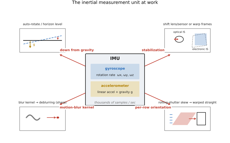
The accelerometer and the gyroscope together form the inertial measurement unit (IMU): the accelerometer measures specific force along three axes (proper acceleration, including the support force measured while resting in gravity), the gyroscope measures rotational rate (angular velocity) about three axes. Between them they tell the camera, at thousands of samples per second, short-term evidence about motion and rotation, with bias, noise, calibration, and integration drift, and that motion record is one of the most useful side-channels in all of computational photography.
It does at least four jobs. First, gravity gives an absolute "down." At rest, its measured specific-force vector opposes gravity, so its direction tells the camera which way is down. This is how a phone auto-rotates, how the camera app draws a level, and how a panorama or a photo can be auto-straightened to a true horizon without ever looking at the pixels. Second, the gyroscope drives stabilization. In optical image stabilization (OIS) the gyro's rotation-rate readings steer a tiny actuator that shifts the lens (or the sensor) in real time to cancel handshake during the exposure, physically counter-rotating the image before it is even recorded. In electronic image stabilization (EIS) the same readings are used after capture to warp each video frame back into alignment, trading a crop of the margins for a smooth result. Third, and most tightly coupled to imaging, the IMU supplies the motion that explains blur and rolling-shutter distortion. If you know how the camera rotated during a long exposure, a calibrated camera/IMU model constrains the rotational blur, the path along which the image smeared, which gives deblurring a head start it would otherwise have to guess (the gyro-aided deblurring idea). And because a CMOS sensor reads out row by row, knowing the camera's rotation across the few milliseconds of readout lets you compute each row's true orientation and warp it back to a common instant, reducing rotational skew, wobble, and "jello" of the rolling shutter. Camera translation, parallax, subject motion, timing error, and exposure blur need additional treatment. That row-by-row, IMU-driven correction is the heart of Chapter 30.6, Video stabilization and rolling-shutter correction; here we simply note that the gyroscope is what makes it tractable, because it measures the camera's motion directly instead of forcing us to recover it from the pixels alone.
34.9.2 Sound: microphones, audio-visual sync, and the visual microphone⧉
A camera that shoots video has microphones, usually several, and that audio is a side-channel in its own right. The obvious job is the soundtrack, but the multi-microphone array also does beamforming (steering sensitivity toward the subject and suppressing off-axis noise) and lets the device estimate the direction a sound came from. The subtler imaging job is synchronization: matching the audio timeline to the video timeline, and matching audio across several cameras that filmed the same event, so that independently captured clips can be aligned by their shared sound. A distinctive clap or beep in two recordings can align recordings more precisely than coarse file timestamps, provided propagation delay, clock drift, and recording latency are accounted for.
The most surprising tie between sound and image inverts the relationship entirely: the visual microphone Davis et al. 2014 recovers sound from silent high-speed video. A nearby sound is a pressure wave, and that wave makes everyday objects (a bag of chips, a plant leaf, a glass of water) vibrate by sub-pixel amounts. Film the object at thousands of frames per second and measure those tiny vibrations from the image (using the same phase-based motion analysis that powers motion magnification), and you can reconstruct the audio that shook it, well enough to recover intelligible speech from a soundproof room through a window. It is a strong example of this chapter's theme: non-visual information can be recovered from images by computation, and we develop it fully in Part 38, Revealing the invisible.
34.9.3 GPS: geotagging and place⧉
The satellite-navigation receiver (GPS and its global cousins) gives the camera its position on Earth, and the camera can write the estimated coordinates into metadata when location access and geotagging are enabled. The immediate payoff is geotagging: photos sort onto a map, cluster by trip, and remember where you stood. The deeper payoff is using location as a prior on content: a photo's coordinates favor the Eiffel Tower over a distant lookalike, narrow a landmark search to one city, or, conversely, let a large enough collection of geotagged photos predict an untagged image's location from its appearance alone. That inversion, recovering position from pixels by using millions of geotagged images, is the idea of Chapter 28.8, Pix 2 GPS. Location also feeds white balance and exposure priors (a beach at noon versus a bar at night) and stitches a day's photos into a coherent trail.
34.9.4 Compass and magnetometer: heading and orientation⧉
The magnetometer measures the local magnetic field, and from it the device derives a compass heading, the absolute direction the camera is pointing. Combined with the IMU's gravity vector, it gives the camera a full absolute orientation in the world frame, not just relative motion. That absolute pointing is what lets augmented reality anchor virtual objects to real directions (so a label stays pinned to the north-facing building as you turn), what orients a captured panorama on the globe and helps the stitcher know roughly how far you swept, and what lets a sky-map or star-finder app know which constellation fills the frame. Where the gyroscope says how fast you are turning, the magnetometer and gravity together say which way you are now facing, and an absolute heading cue can help limit gyro drift. Nearby metal and electronics distort the magnetic field, so calibration and image-based corrections remain necessary.
34.9.5 Near-infrared: the cut filter, dark flash, and NIR-assisted denoise⧉
Silicon sees well into the near-infrared (NIR), past where the eye stops, which is usually a nuisance: stray NIR would corrupt color, so almost every consumer camera bolts an infrared-cut filter in front of the sensor to throw it away (the long-wavelength leakage we met in the sensor's spectral-response curve). But NIR is information, and several computational-photography tricks deliberately keep it. A dark flash illuminates a scene with a burst of (near-)infrared light that is nearly invisible to people in the room but bright to the sensor, so you can capture detail in the dark without a blinding visible flash. More generally, an NIR image can provide a cleaner structural guide when illumination, exposure, and atmospheric conditions favor it, so it can guide denoising of the noisy visible frame, transferring the NIR channel's edges and texture onto the color image, a cross-channel version of guided filtering. Material appearance and edges can differ between NIR and visible light, so indiscriminate detail transfer can create false structure. Because consumer cameras filter NIR out by default, this material now lives with the other deferred topics in Part 46, Missing stuff, bugs; the wavelength a normal camera discards is, for someone willing to keep it, an additional illumination channel that requires suitable optics, sensing, and often active lighting.
34.9.6 Temperature: dark-current compensation⧉
A thermometer on or near the image sensor keeps the other measurements trustworthy. Even in total darkness a photosite accumulates a trickle of thermally generated electrons (dark current) that adds a spurious, temperature-dependent signal and noise to every pixel, roughly doubling with each several-degree rise. Knowing the sensor's temperature lets the camera compensate: subtract the expected dark level, adjust the noise model, and decide when a long exposure needs a dark-frame subtraction. It is a small correction, but subtraction removes the expected offset, not the dark-current shot noise. Cooling reduces the underlying dark current; subtracting an independently measured dark frame adds its own noise unless it is averaged sufficiently. Again, metadata makes the pixels more interpretable.
None of these sensors makes a picture. Each adds information about the picture: its location, orientation, stability, cleaning it, time-aligning it, or telling its signal from its noise. The image sensor is the headline act; the side-channels are why a modern photograph knows where, when, which way up, and how steadily it was taken, and that knowledge is woven through nearly every computational method in this book.