22.8 Focus⧉
In the ideal thin-lens model with parallel lens and sensor planes, one scene plane is in focus on the sensor. Real lenses can have field curvature, and tilted systems change the orientation of the focus plane. Everything closer or farther blurs, gently at first and then badly, into the circles of confusion that FUNDAMENTALS made precise. Focusing is the act of choosing which scene plane that is, sliding the in-focus plane forward or back through the scene until it lands on whatever you care about. Mechanically, this means changing the optical configuration or lens-to-sensor distance; the required travel depends strongly on focal length and subject distance. This chapter is about that mechanical act. The harder question, given the blurry image the sensor sees right now, of which way to move and by how much, is the subject of the next chapter on autofocus.
22.8.1 Focus mechanics⧉
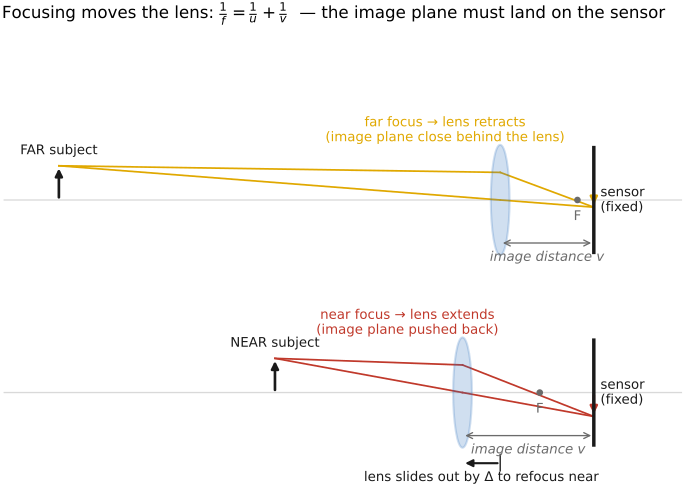
Start with what "focus" physically is. The thin-lens conjugate relation from FUNDAMENTALS, $1/f = 1/u + 1/v$, ties the object distance $u$ to the image distance $v$ at which that object comes to a sharp point. An object at infinity ($u \to \infty$) focuses at $v = f$, right at the focal length; pull the object nearer and $v$ grows, so the sharp image moves back, away from the lens. To keep that sharp image pinned on a fixed sensor, then, the camera must move the lens (or a focusing group inside it, or the sensor) forward as the subject comes closer. That motion is focusing, and Figure 1 shows the geometry: focusing slides the system so that the chosen conjugate lands exactly on the sensor.
How far must the lens move? Write subject closeness as $D=1/u$, in inverse meters. The thin-lens equation gives
Near infinity, $fD$ is small and $\Delta v\approx f^2\Delta D$. Long lenses therefore need much more extension than short ones for the same change in subject diopters. The sensitivity grows as the subject approaches. A focus ring's allocation of angle depends on its mechanical or electronic mapping, but substantial optical travel is needed in the near field (Figure 22.8.2). This finite travel is what the focusing actuator must provide and calibrate.
Before autofocus existed, the photographer supplied that decision by eye, aided by a family of manual-focus aids (ground glass, the split-image and microprism screens, and the coincidence rangefinder) that make defocus visible; because they are as much about the photographer's craft as about optics, and because their disparity principle is the direct ancestor of phase-detection autofocus, they are covered with the photographer's focus controls in Chapter 5.3, Viewpoint, lenses, and focus (PHOTOGRAPHY part, §3.3).
22.8.2 Focusing a compound lens: beyond unit focusing⧉
The thin-lens picture above quietly assumed a single element that moves as a rigid whole. The simplest way to focus is unit focusing (also whole-group or extension focusing): translate the entire lens (or, equivalently, the sensor) along the axis, changing the lens-to-sensor spacing until the conjugate lands home. It is exactly Chapter 2.3, Lens Image formation that the cleanest focus is to move the sensor, or the whole lens, and let $1/f = 1/u + 1/v$ do the rest. Bellows view cameras, most macro extension setups, and the tiny fixed lens of a phone all focus this way. Its cost is that you have to move the whole assembly, which for a heavy telephoto is slow, and the barrel changes length as it focuses.
A compound lens, though, is not one rigid element. It is several groups, and that freedom opens other places to move glass, each with its own tradeoffs. Figure 2 traces rays through a multi-element lens under each scheme, with a slider that sets the subject distance so you can watch which group has to move to keep the image on the sensor.
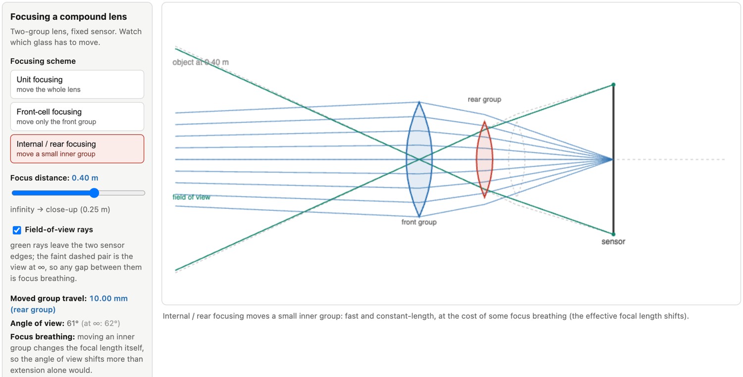
Front-cell focusing moves only the front group, usually by threading it in and out on a helicoid. It is mechanically cheap and was standard on older zooms and inexpensive primes. The drawbacks are real: the front element rotates as it extends (awkward for polarizers and graduated filters), the lens is hard to weather-seal, and because the front group carries much of the aberration correction, image quality drifts as you focus close.
Internal focusing (IF) and the closely related rear focusing (RF) move a small group inside the lens instead. Because that group is light, an actuator can drive it fast and precisely, which is what makes quick autofocus practical; the lens keeps a constant physical length, the front element does not rotate (filters stay put), and the barrel is easy to seal. Many autofocus lenses use internal or rear focusing. The price is that shuffling an internal group changes the lens's effective focal length slightly as it focuses, which shows up as focus breathing: the field of view zooms a little as focus is pulled. In video that breathing is visible and distracting during focus pulls, and in focus stacking or depth-from-defocus it means consecutive frames do not register at the same magnification and must be re-aligned (cross-ref Depth of field and the focal-stack discussion below). Cine lenses often seek to minimize breathing, and some cameras correct the residual digitally, but breathing is not exclusive to internal focusing: whole-lens extension also changes image scale.
The most elaborate schemes move two groups by different amounts as you focus, a floating-element (or dual-floating) design. The extra degree of freedom lets the designer hold aberration correction across the whole focus range, especially at close distances where a fixed-group lens falls apart; this is why fast primes and true macro lenses advertise floating elements. The theme across all of these is the same tradeoff: unit focusing is optically clean but mechanically clumsy, and every internal scheme buys speed, sealing, and constant length at the cost of some focus breathing or correction drift that the designer then has to fight back down.
22.8.3 Focus actuators⧉
Whatever group moves, something has to move it, and on a modern lens that something is a motor, not the photographer's hand. In most autofocus lenses the focus ring is not mechanically connected to the glass at all: turning it sends an electronic signal to a motor that drives the focusing group. This is focus-by-wire, and the decoupling is what makes fast, silent, programmable focus possible. The controller can respond to a touchscreen tap and use calibrated lens-position information. Travel speed, settling time, power needed to hold position and encoder availability depend on the actuator. It also means the focus system is free to command any supported lens position, subject to travel and settling time, so the only question left is what position to command, which is the algorithm problem of the next chapter.
On large-camera lenses (interchangeable-lens cameras, cine lenses) the motor has to move groups that can weigh grams to tens of grams, and there is room to do it. The oldest AF lenses used a DC micromotor turning a gear train, cheap but slow and audibly whirring. The workhorse of the last three decades is the ring-type ultrasonic motor (Canon USM, Nikon SWM, Sony SSM): a piezoelectric ring sets up a traveling wave that drives a rotor directly, giving strong, fast, nearly silent focus that holds position unpowered and allows full-time manual override. For video, stepper motors (STM) move the group in small, smooth, quiet increments, ideal for the steady focus pulls that autofocus makes during recording. And for light internal groups, linear motors (including voice-coil designs) slide the group straight along the axis with very fast, precise settling, making them useful for fast focus control.
Phones face the opposite constraints: a lens a few millimeters across, no room for a ring motor, and a hard demand for silence, low power, and speed. The near-universal answer is the voice-coil motor (VCM): a small coil around the lens barrel sits in a permanent magnetic field, and current through the coil pushes the whole tiny lens against a spring, moving it a fraction of a millimeter. This is unit focusing at micro scale, the entire lens translating relative to the sensor, a practical design for many small camera modules. Cheap VCMs run open-loop (current maps roughly to position), while better modules add a Hall-effect position sensor for closed-loop control, which is what gives repeatable focus and can support coordinated focus and stabilization control. Newer actuator families push on the same envelope: shape-memory-alloy (SMA) wires that contract when heated, piezoelectric and MEMS actuators, all chasing more travel and better precision in a package measured in millimeters. The constraint that shapes phone focus, and much of computational photography's reliance on it, is that this microscopic, cheap, repeatable actuator can be fired many times a second, which is what makes the continuous, per-frame refocusing of a phone's preview and its autofocus tricks possible.
Nano USM is a distinct ultrasonic actuator, not a voice coil: Canon describes a piezoelectric element driving linear movement. The output motion can be linear even when the force-generation principle differs (Canon lens technology).
22.8.4 Focus stacking, macro, and focusing rails⧉
Focusing gets hardest exactly where you need it most precise: up close. At macro magnifications the depth of field collapses to millimeters or less (FUNDAMENTALS), so a single frame cannot hold even a small three-dimensional subject sharp from front to back. There are two mechanical responses, and they differ in a way that matters for perspective.
The first is focus stacking: capture a stack of frames at stepped focus settings, then combine them by keeping, at each pixel, the sharpest slice. This is the depth-from-focus machinery of the next chapter used to build an all-in-focus image rather than a depth map, and its full treatment lives in Depth of field; many cameras now automate the stepping as in-camera focus bracketing. The catch is the focus breathing noted above: because internal focusing changes magnification slightly from frame to frame, the slices are at subtly different scales and must be registered before they can be merged.
The second response avoids refocusing altogether. Instead of changing the lens's focus setting between frames, mount the whole camera on a focusing rail and slide it forward by a fixed step for each shot. The lens stays at one focus setting, so its magnification and aberration correction do not change; what changes is the camera-to-subject distance, moved mechanically. This is the standard rig for high-magnification macro and for microscope-objective work, and it is easily motorized (rigs like StackShot step the rail and trigger the shutter automatically). But moving the whole camera moves the entrance pupil, which means it also changes the perspective slightly from frame to frame, the near parts of the subject shifting against the far parts, so the slices have to be aligned for viewpoint as well as scale before stacking. It is a real tradeoff against in-place refocusing: the rail keeps the optics constant but changes where you are looking from, while refocusing changes the optics and may also shift the entrance pupil. Landscape photographers meet a gentler version of the same idea, blending two or three frames focused near and far to carry a foreground and a horizon both sharp.
22.8.5 Optional background: viewfinder optics⧉
A reflex finder diverts light from the taking lens onto a focusing screen at an optically corresponding image plane. A roof prism or mirror assembly makes the image convenient to view through an eyepiece. Focus agreement depends on alignment between the screen, lens and film or sensor plane. During capture the mirror moves out of the optical path.
A separate optical finder has a different viewpoint from the taking lens, creating a framing offset that matters most nearby. A rangefinder adds an optical baseline for focusing but still does not show the taking lens's defocus. An electronic finder displays the processed sensor feed through a magnifying eyepiece. Its limits concern sampling, processing, lag and emitted light as well as its eyepiece optics.
Coverage specifies how much of the captured frame is shown. Finder magnification specifies the apparent view under defined lens and focus conditions; it should not be compared without those conditions. These properties affect how confidently the photographer can judge framing and focus.
22.8.6 Manual-focus aids: making the focal plane visible⧉
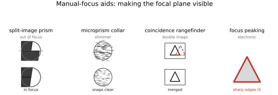
Before autofocus, the photographer made the focus decision by eye, helped by optical cues engineered to make defocus visible. Their working principles reappear, mechanized, in phase-detection autofocus (Figure 22.8.4). The aids fall into two families by where they judge focus: through the taking lens, on the focusing screen of a single-lens reflex (SLR), or through a separate optical baseline, in a rangefinder.
Ground glass. The oldest aid is to look at the image the lens actually forms. A finely ground, diffusing surface at the film plane catches the aerial image and scatters it toward the eye, sharp where the lens is focused and smeared where it is not. A view camera is focused this way, on a ground-glass back under a dark cloth, and an SLR carries a small version of it: the reflex mirror sends the image up to a focusing screen viewed through the pentaprism. The whole matte field is a focus aid, usable anywhere in the frame. An SLR views at the lens's maximum aperture and stops down only for the exposure, so the screen is as bright as the lens allows and its depth of field as shallow, which is what makes focus visibly snap in and out. A fast lens gives a bright screen with a thin in-focus zone; a slow zoom gives a dim screen with so much depth of field that small focus errors are hard to see.
The split-image prism. Many SLR screens carry, at their center, a pair of opposed wedge prisms that cut the image into two halves. Each wedge passes light from one side of the lens's exit pupil toward the eye, so the two halves are views from opposite sides of the aperture: a small stereo baseline inside a single lens. At focus the halves line up; out of focus they are displaced sideways, and the photographer turns the focus ring until a broken line becomes continuous. This is a disparity measurement, and phase-detection autofocus makes the same comparison between opposite parts of the pupil with a sensor instead of an eye. The design has a cost: because each wedge relies on light from the edge of the pupil, a lens slower than the aperture the prism angle was designed for (commonly somewhere around $f$/4 to $f$/5.6) leaves one half dark, so the aid fails with slow lenses or when the lens is stopped down.
The microprism collar. Around the split spot, many screens place a ring of tiny pyramidal facets, each a miniature split prism. An out-of-focus image seen through it breaks into a coarse shimmer that resolves abruptly into a clean image at focus. The split prism gives a precise line-up on one edge; the microprism gives a quick cue over a small area. It needs light from across a wide pupil too, and dims with slow lenses for the same reason.
The coincidence rangefinder. The other family judges focus outside the taking lens. A rangefinder camera views the subject through two windows a known distance apart and superimposes the two views in a patch of the finder. A mirror or prism coupled to the focus ring turns one view until the double image merges, which solves the triangulation of Chapter 36.1, Multiple view geometry by hand: nearer subjects need a larger rotation to bring the views together. Because the finder does not look through the taking lens, it stays bright with slow lenses and in dim light and suits wide-angle lenses well. It cannot show depth of field, it suffers parallax between the finder and the lens, and its accuracy depends on its effective baseline, magnification and calibration, which limits it with long lenses.
Electronic aids. Electronic viewfinders and live view compute the cue from the sensor image. Focus peaking outlines the edges with the most high-frequency contrast in a bright color, since in-focus edges carry the most. It is a contrast cue, so noise and already sharpened detail can produce misleading outlines. Magnified live view enlarges a patch so the photographer can inspect the relevant feature directly. Neither needs a wide aperture or moving optics, and both do what the glass aids did: make the thinness of the focal plane visible.
22.8.7 Optional background: focus control in cinema lenses⧉
A focus pull changes the plane of sharpness during a shot. A lens with substantial focus breathing also changes framing. Cinema-oriented designs often seek reduced breathing, repeatable focus travel and calibrated markings so a pull can be rehearsed. A parfocal zoom seeks to hold focus while focal length changes; its performance still depends on setup and tolerances.
T-stop markings allow exposure to be matched across lenses with different transmission. A continuous iris allows an exposure change without discrete clicks. Gear rings, mechanical stops and consistent dimensions can make lens changes easier in a rig. In practice, the focus ring turns through a long arc, often around 270 to 300 degrees against a stills lens's short throw or focus-by-wire, so a focus puller can set witness marks for each actor's position and hit them take after take; gear rings in the standard 0.8 module let one follow-focus unit or lens motor fit every lens in a set; and a set of primes matched for color, contrast and out-of-focus rendering lets shots from different lenses be intercut without a visible jump. Some lenses prioritize small size or autofocus instead. These are production requirements, not a promise that every cinema lens has zero breathing, identical rendering or a particular mechanism.