2.3 Lens Image formation⧉
A pinhole forms an image by throwing away almost all the light — only the rays through the tiny hole survive. That is a serious problem: a pinhole sharp enough to make a crisp image passes so little light that exposures take seconds, and (as the previous part's diffraction limit warned) shrinking the hole eventually blurs the image anyway. We want to collect a wide cone of light from each scene point — far more light than a pinhole — and still focus it to a single image point. That is exactly what a lens does, and the price it charges is a single plane of focus and a finite depth of field.

This chapter follows that bargain in three steps. First, a single lens bending light by refraction — Snell's law at two curved surfaces, with the Fermat "equal optical path" view alongside. Then the thin lens: the small-angle linearization of that law that hands us the focus equation, conjugates, magnification, and the f-number in a few clean lines. Finally depth of field: the range of distances a single focus plane keeps acceptably sharp, the circle of confusion that defines it, and the surprising fact that — at fixed framing — it barely depends on focal length at all. Throughout, we are using the paraxial model; what it throws away (aberrations, color) points forward to the OPTICS part.
2.3.1 Single lenses: refraction and Snell's law⧉
A real lens is a piece of glass bounded by two curved surfaces — two interfaces, air-to-glass and glass-to-air. It works by refraction: the bending of light as it crosses between media of different refractive index, introduced in Light and physics. At each interface a ray bends according to Snell's law (Descartes' law, if you are French):
where $n_1, n_2$ are the refractive indices on the two sides and $\theta_1, \theta_2$ the angles measured from the surface normal. Drawn on a deliberately thick lens, with the two interfaces far apart, you can watch the bending happen twice — once entering the glass, once leaving — and the net effect of the two curved surfaces is to steer a parallel bundle of rays so they converge to a focal point (Figures 2 and 3). A curved interface bends each ray by an amount that depends on where it strikes the surface, and the curvature is chosen so that all the rays from one scene point are redirected to meet at one image point. That is the whole job of a lens: bend a wide cone back to a point.


A second, equivalent view: Fermat and equal path lengths. There is a wave-side way to see why a lens focuses, worth holding alongside the ray picture because it explains why the curvature has to be just so. A lens focuses because every ray from the object to the focus travels the same optical path length — geometric distance weighted by the refractive index of each medium it crosses (Figure 2.3.4). A ray through the thick center of the lens takes a longer geometric path but spends more of it in slow glass; a ray skimming the thin edge takes a shorter geometric path, almost entirely through fast air. The lens's shape is exactly what makes these trade off perfectly, so all the rays arrive at the focus in phase and interfere constructively, building a bright point. Snell's law (rays bending) and Fermat's principle (equal optical paths) are two descriptions of the one fact; either predicts the same focus.

How strongly a lens bends light — its focal length — is set by the curvature of its two surfaces and the glass index, through the lensmaker's equation:
with $R_1, R_2$ the radii of curvature of the two surfaces. More curvature, or a higher index, means a shorter focal length (stronger bending). We can watch this happen directly by solving the wave equation: send a point source's diverging wave into a slab of glass and let the wave evolve (Figure 2.3.5). Because the glass is thickest on the axis, it slows the middle of each wavefront most — and that is exactly enough to bend a diverging wavefront into a converging one, which collapses to an image point on the far side. The focus lands where the lensmaker's and imaging equations say it should, and tightening the curvature or raising the index pulls it inward, just as $1/f=(n-1)\,2/R$ predicts.

This whole picture, though, already assumes the rays make small angles with the axis — it is paraxial. At large angles the rays from a single point do not all meet at exactly one place, and the image degrades; those departures are aberrations, the subject of the OPTICS part, where compound lenses (many elements) are designed to cancel them. Our own eyes are refracting systems too: the cornea and the lens are the two main bending elements, doing for the retina what a camera lens does for the sensor.
2.3.2 Thin lens optics⧉
The two-interface, Snell's-law lens is accurate but cumbersome. For everything in this book except the dedicated optics chapters, we use a linearization of it called the thin lens (Figure 2.3.6). Collapse the two interfaces into a single plane of zero thickness, assume all angles are small, and let all the bending happen once, at that plane. Two construction rules then locate any image:
- A ray arriving parallel to the axis leaves through the focal point $F$, at distance $f$.
- A ray through the center of the lens passes undeviated — straight through, exactly as through a pinhole. (This second rule is why a thin lens has the same perspective as a pinhole: the central ray is the chief ray, so the projection geometry of the previous chapter carries over unchanged. The lens only adds light-gathering and focus on top of pinhole projection.)
The thin lens is precisely first-order (paraxial) optics: replace $\sin\theta \approx \theta$, keeping only the linear term of the sine. Keep the next term, $\sin\theta \approx \theta - \theta^3/6$ (third-order optics), and out pop the classical Seidel aberrations — spherical aberration, coma, astigmatism, and the rest. So "the thin-lens linearization" and "a lens with no aberrations" are literally the same assumption, dropped at the same place. The OPTICS part keeps the cubic term.

The focus equation. Place an object at distance $u$ in front of the lens; its sharp image forms at distance $v$ behind, and the two are tied by the thin-lens (conjugate) equation:
Read it back: the reciprocals of the object and image distances add to the reciprocal of the focal length. An object at infinity ($1/u \to 0$) images at exactly $v = f$ — that is what "focal length" means for a lens, the image distance for a far subject. As the object comes closer, $1/u$ grows, so $1/v$ must shrink: the image moves farther back. Focusing a camera is nothing more than adjusting $v$ — moving the lens, or the sensor — until the image of the subject you care about lands exactly on the sensor (Figure 2.3.7). Each object distance has exactly one image distance that focuses it — they are conjugates — and an object placed right at the focal point $F$ sends out rays that exit parallel, imaging at infinity (the reverse of the first case).
Symmetry and reversibility. Notice that the focus equation is symmetric in the two distances: writing it $1/f = 1/s_o + 1/s_i$, with $s_o$ the object distance and $s_i$ the image distance, nothing distinguishes the two — swap them and the equation is unchanged. This is no accident; it is the reversibility of light paths made arithmetic. Object and image are conjugate: send light the other way, and the rays retrace exactly the same path, so the old image plane now acts as object and the old object plane as image. The two are conjugate planes, and the magnification swaps with them — $m = -s_i/s_o$ simply inverts ($m \to 1/m$) when you exchange the roles. This object↔image reciprocity runs all through optics: it is why a lens images perfectly well either way round, and (a case we meet in the OPTICS part) why a lens's entrance and exit pupils are themselves conjugates — images of the same aperture seen from the two sides.

The convenient lie. It is worth being honest about what we just did. Real glass refracts by Snell's law, $n_1\sin\theta_1 = n_2\sin\theta_2$, at each curved surface (previous section) — exact, but trigonometric and messy. The thin lens is the linearization of that law: for rays staying near the axis and not too steep, $\sin\theta \approx \theta$, the angle and its sine agree, and the bending becomes proportional to the angle. That single small-angle (paraxial) swap buys us everything tidy on this page. It is exactly why the focus equation $\tfrac{1}{f} = \tfrac{1}{u} + \tfrac{1}{v}$ comes out so clean, and why "every ray from one object point converges to one image point" is true in the model: with $\sin\theta\approx\theta$ a single object point images to a single, perfectly sharp point — stigmatic imaging — and a parallel bundle from a point at infinity converges to a single point in the focal plane. A real lens only approximates this; the rays that wander too far from the axis miss the ideal point, and those departures from the paraxial assumption are the aberrations — spherical aberration, coma, and the rest (the margin note above, and the OPTICS part).
The idealization drops color too. The model assumes one refractive index $n$, but the real $n$ varies with wavelength — dispersion — so red and blue rays bend by slightly different amounts and focus at slightly different places: chromatic aberration. The thin lens pretends every wavelength shares one $n$ and therefore one focus. So read $1/f = 1/u + 1/v$ for what it is: the convenient lie that linearizes Snell's law and throws away color, accurate enough that the whole rest of the book can lean on it, and wrong in precisely the ways the OPTICS chapters spend their time correcting (chromatic aberration in particular — forward ref: OPTICS part).
The image is inverted and resized; the magnification is
the ratio of image to object distance (the minus sign records the flip). Finally, the lens has an aperture — the diameter $D$ of the opening that admits light — and photographers describe it not by $D$ directly but by the f-number
the ratio of focal length to aperture diameter. A small f-number ($f/1.4$) is a wide opening; a large one ($f/16$) is a narrow opening — the number is under the divider, so it runs backwards from how much light gets through. The f-number controls two things at once, exposure and blur. We meet the blur — depth of field — next; the exposure side of the same $f/D$ ratio is taken up in the camera chapter (forward ref).
2.3.3 Depth of field⧉
Set a lens to focus on one plane, and objects exactly on that plane image sharply. Objects nearer or farther do not — and how much nearer or farther you can stray before the blur becomes objectionable is the depth of field (DoF). It is one of the photographer's main creative controls: a portrait with a melting, out-of-focus background, and a landscape crisp from the foreground flowers to the distant peak, are both choices about depth of field.
The circle of confusion. Start with one out-of-focus point (Figure 2.3.8). A point at the focus distance sends a cone of rays through the lens that reconverges exactly on the sensor — a sharp point. A point too far away focuses in front of the sensor, so by the time its cone reaches the sensor it has opened back up into a small disk; a point too near focuses behind the sensor and likewise lands as a disk. That blur disk is the circle of confusion. A point still counts as "sharp" as long as its circle of confusion stays smaller than some acceptable diameter $c$ — set by the sensor's resolution and how large you will view the print (for 35 mm film, $c$ is traditionally about 0.02 mm). The disk grows with the aperture (a wider opening, a fatter cone, a bigger disk) and with the point's distance from the focus plane (zero exactly at focus, growing both ways) (Figure 2.3.9).


The double cone, and the near and far limits. The simplest picture lives in object space: a double cone in front of the lens, its waist sitting on the focus plane, whose width at any depth is the blur that a point there would produce (Figure 2.3.10). Depth of field is the range of object distances whose circle of confusion stays within $c$ — bounded by a near limit (closest still-sharp distance) and a far limit (farthest). The derivation is similar triangles, the recurring move of this part: on the image side, follow the converging cone from the aperture $D$ to where it would focus, and set the disk where it crosses the sensor equal to $c$; combined with the conjugate relation $1/f = 1/u + 1/v$, this fixes the near and far object distances (Figures 9, 10, and 11). The full formulas are in the optics references; the qualitative results are what you carry around, and they all point the same way: depth of field grows with a smaller aperture (larger $N$), a shorter focal length, and a greater focus distance (Figure 2.3.13). Stopping down is the photographer's main knob — but it costs light, so it forces a longer exposure or a higher ISO (more noise), and stopped down too far, diffraction softens everything (previous part). You can only push it so far.


Hyperfocal distance. There is one focus setting that wrings the maximum depth of field out of a lens. Focus at the hyperfocal distance
and everything from $H/2$ all the way to infinity falls within the tolerance $c$ (Figure 2.3.14). This is the landscape photographer's trick — Ansel Adams used it constantly: focusing at infinity instead wastes the whole sharp zone between $H/2$ and $H$, whereas focusing at $H$ buys it back for free.

The surprising invariance. Here is the conclusion the lecture flags as important, and it overturns a common belief. "Telephoto lenses have shallow depth of field" is not really true as stated. For a fixed framing — you keep the subject the same size in the frame — and a fixed f-number, the depth of field in object space is essentially independent of focal length (Figure 2.3.15). Switch from a 28 mm to a 100 mm lens and, to keep the subject the same size, you must step back; stepping back deepens the depth of field by exactly as much as the longer focal length shrinks it, and the larger physical aperture of the long lens (same f-number $N = f/D$ means $D$ grew with $f$) cancels the rest. The two effects exactly compensate. So shallow depth of field is really about magnification — how large the subject is on the sensor — not focal length per se.
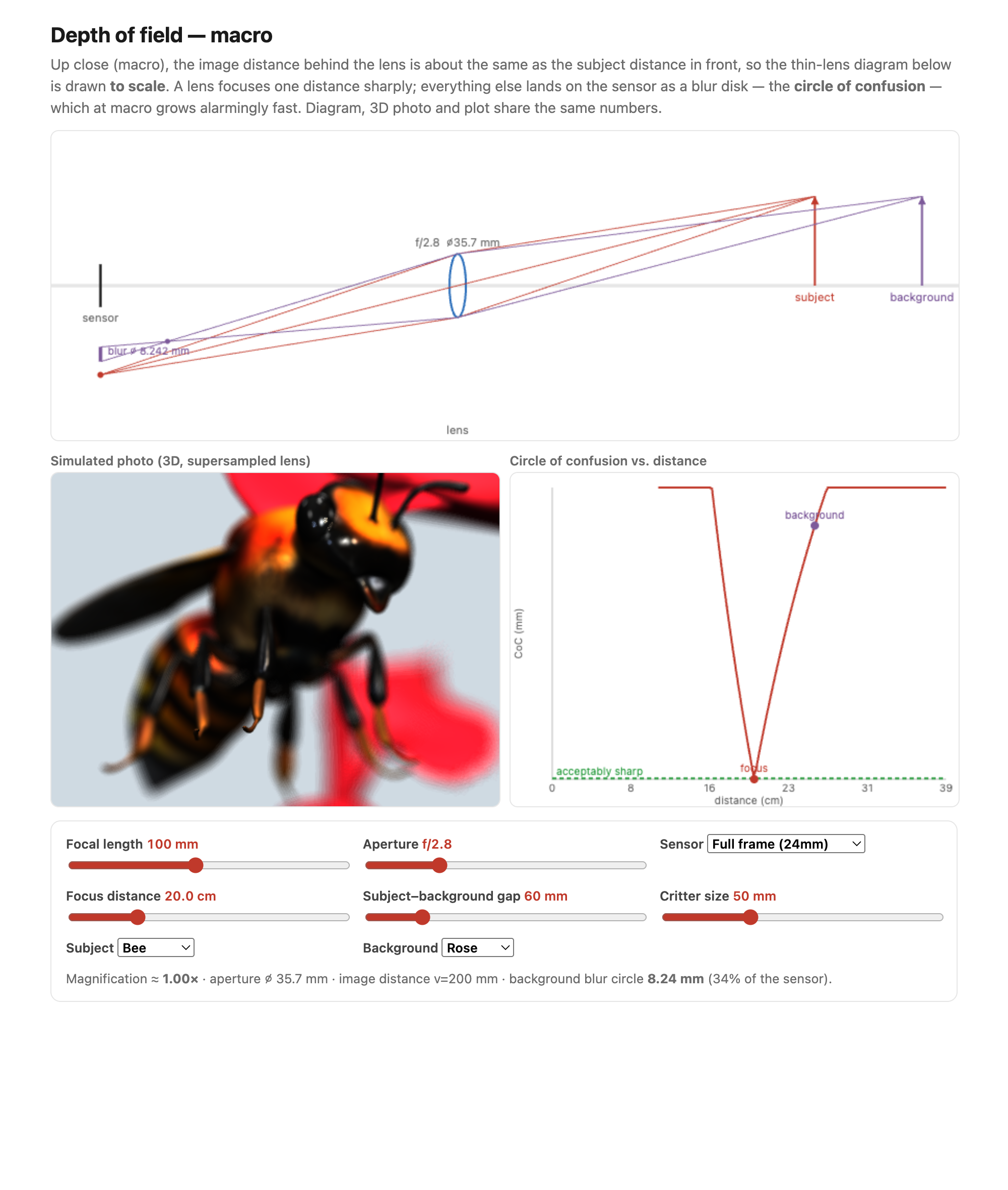
This is genuinely useful: for macro work, where depth of field is precious, you can change your working distance — back off to make room for lights, say — without changing the depth of field at all, as long as you re-frame to the same magnification. The background does still look more blurred through the long lens, but that is because the long lens magnifies the already-out-of-focus background disks, not because the depth-of-field band changed.

Defocus is not a blur of the image. It is tempting to think you could fake shallow depth of field by simply blurring a sharp photo — convolving it with a disk. You cannot, and the reason matters (Figure 2.3.16). The circle of confusion depends on each point's scene depth, not on its position in the image, so the blur is spatially varying in a way tied to 3D structure rather than pixel coordinates. Worse, at depth discontinuities — the edge of a foreground object against a far background — occlusion comes into play: the blurred foreground should bleed over the background, and the background that the foreground hides should partly show through the foreground's blur, neither of which a flat 2D blur can do. Depth of field is not a convolution of the image. This is exactly why naive "portrait mode" fakes look wrong at hair and edges, and why depth-aware and light-field methods (Advanced part) — which know each pixel's depth, or capture the rays directly — do so much better.

Sensor size scales depth of field. Finally, a fact that explains your phone. Shrink the sensor while keeping the field of view (FOV), and both the circle of confusion $c$ and the physical aperture $D$ shrink in proportion, so depth of field grows linearly as the sensor shrinks. Phone cameras therefore have enormous depth of field — almost everything is in focus, which is why they must fake background blur computationally (portrait mode). The same fact makes macro photography easier on small sensors: a scaled-down camera photographs a scaled-down world, gaining both closer minimum focus and more depth of field for free — except for diffraction, since shrinking the camera does not shrink the wavelength of light.